
Artificial photosynthesis module

a photosynthesis module and artificial technology, applied in the direction of physical/chemical process catalysts, metal/metal-oxide/metal-hydroxide catalysts, oxygen/ozone/oxide/hydroxide, etc., can solve the problem of difficult to improve the reaction efficiency, limited size of working electrodes in which oxygen is generated, and form electrodes with film thickness

Active Publication Date: 2018-12-20
FUJIFILM CORP +1
View PDF2 Cites 2 Cited by
  • Summary
  • Abstract
  • Description
  • Claims
  • Application Information

AI Technical Summary

Benefits of technology

The invention aims to solve the problems in existing technology by providing an artificial photosynthesis module that has high reaction efficiency. This means that the module can react faster and more effectively than previous versions.

Problems solved by technology

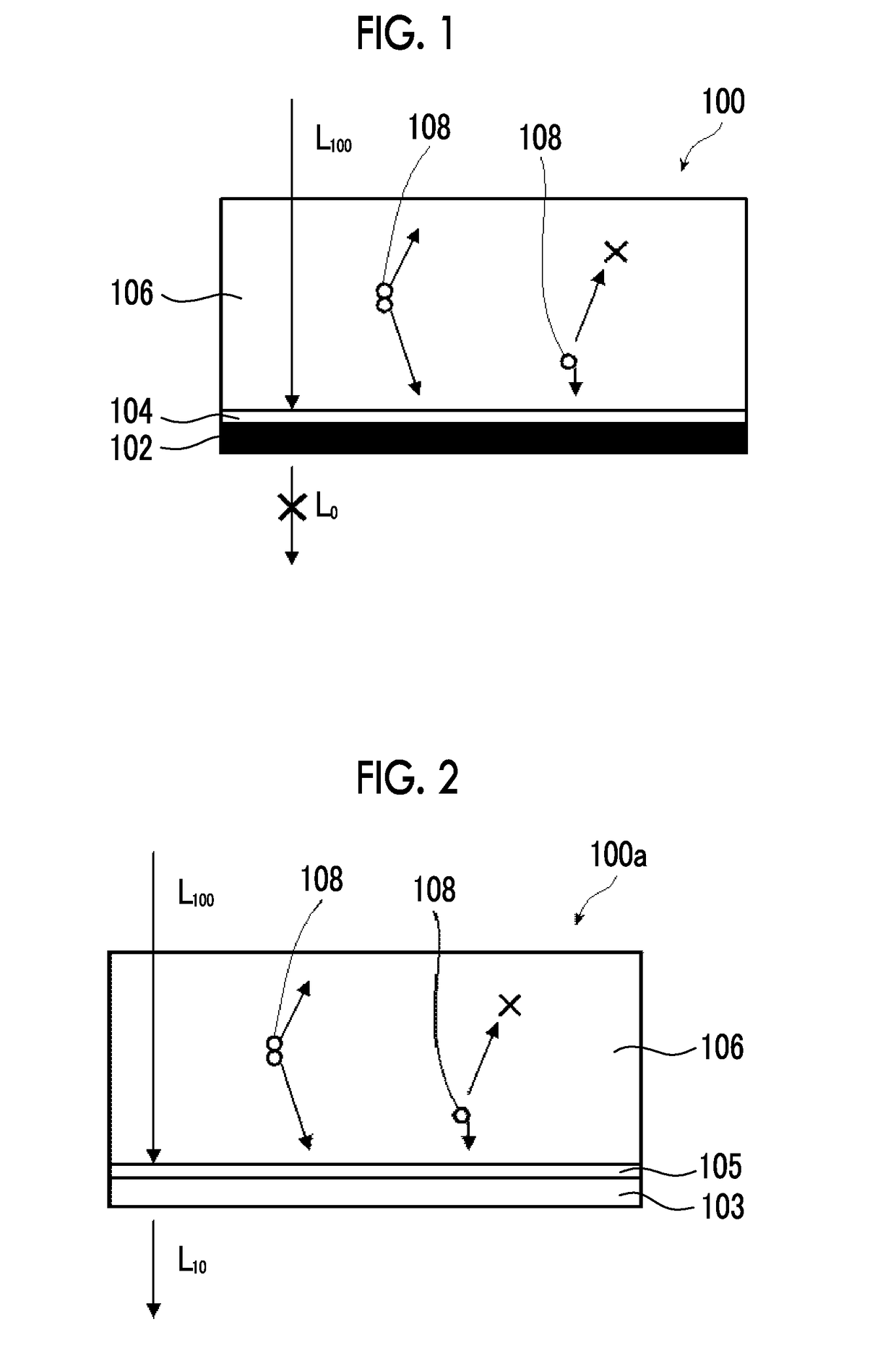
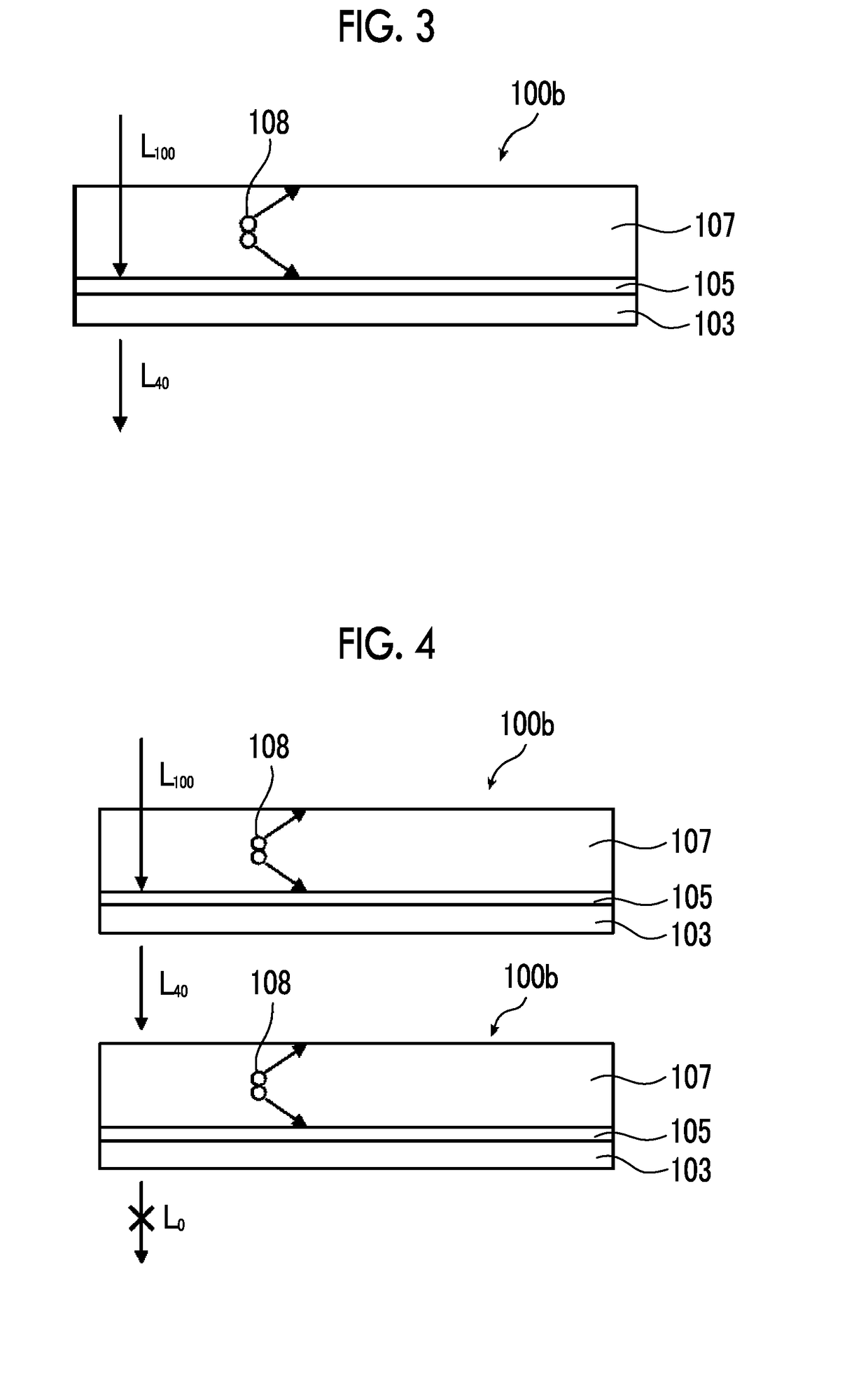
However, in the related art, it is difficult to form an electrode with a film thickness to such an extent that 100% of the light in the absorption wavelength region can be absorbed because of the mobility and the carrier lifetime of carriers, for example, electrons, and holes that move inside the water decomposition photocatalyst electrode.
For this reason, it is difficult to improve the reaction efficiency.
Additionally, in JP2013-213231A, the working electrode in which oxygen is generated, and the counter electrode in which hydrogen is generated are overlapped with each other in an incidence direction of the light and are disposed in tandem, the size of the working electrode in which oxygen is generated is limited, and a reaction field where oxygen is generated is limited.
In this case, it is difficult to make the reaction efficiency per installation area of the water decomposition apparatus high.

Method used


Image

  • Artificial photosynthesis module
  • Artificial photosynthesis module
  • Artificial photosynthesis module

Examples


example 1

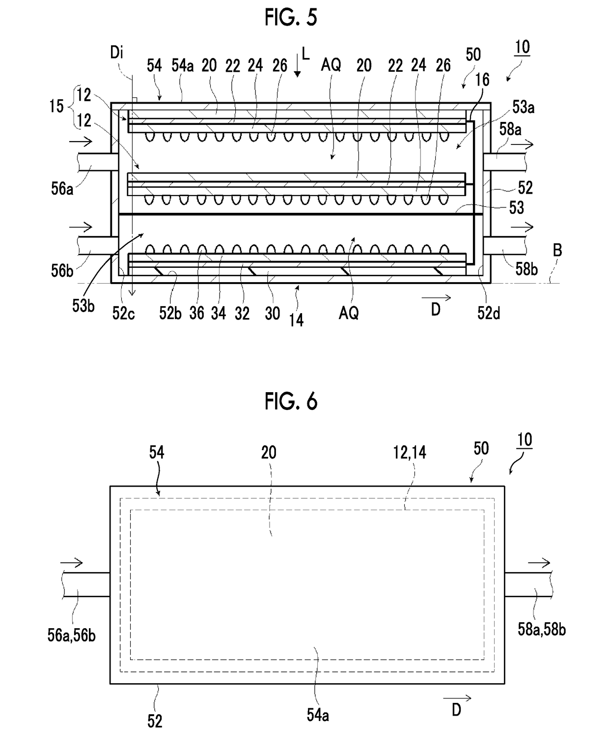
[0186]Example 1 is an artificial photosynthesis module 60 illustrated in FIG. 18. In addition, in an artificial photosynthesis module 60 illustrated inFIG. 18, the same components as those of the artificial photosynthesis module 10 illustrated in FIG. 5 will be designated by the same reference signs, and the detailed description thereof will be omitted.

[0187]The artificial photosynthesis module 60 illustrated in FIG. 18 has two oxygen generation electrodes 12 and one hydrogen generation electrode 14, and the two oxygen generation electrodes 12 and the one hydrogen generation electrode 14 are disposed in series in the traveling direction Di of the light L. The light L is incident from the oxygen generation electrode 12 side, and all the oxygen generation electrodes 12 have the first co-catalyst 26 on the side opposite to the incidence side of the light L with respect to the first substrate 20.

[0188]A method of making the oxygen generation electrodes 12 and the hydrogen generation ele...

example 2

[0197]Example 2 is an artificial photosynthesis module 62 illustrated in FIG. 19. The artificial photosynthesis module 62 of Example 2 has the same configuration as the artificial photosynthesis module 60 illustrated in FIG. 18 except that, in the first oxygen generation electrode 12, the first co-catalyst 26 is provided on the incidence side of the light Las compared to Example 1.

example 3

[0198]An artificial photosynthesis module of Example 3 has the same configuration as the artificial photosynthesis module 60 illustrated in FIG. 18 except that the number of oxygen generation electrodes 12 is three (refer to FIG. 14) as compared to Example 1.


PUM

PropertyMeasurementUnit
thicknessaaaaaaaaaa
thicknessaaaaaaaaaa
light transmittanceaaaaaaaaaa

Abstract

An artificial photosynthesis module includes an oxygen generation electrode having a first photocatalyst layer that decomposes water with light to generate oxygen, and has a first substrate, a first conductive layer, a first photocatalyst layer, and a first co-catalyst, and a hydrogen generation electrode that decomposes water with light to generate hydrogen and has a second substrate, a second conductive layer, a second photocatalyst layer, and a second co-catalyst. This provides an artificial photosynthesis module with high reaction efficiency.

Description

CROSS-REFERENCE TO RELATED APPLICATIONS[0001]This application is a Continuation of PCT International Application No. PCT / JP2017 / 003987 filed on Feb. 3, 2017, which claims priority under 35 U.S.C. § 119(a) to Japanese Patent Application No. 2016-032263 filed on Feb. 23, 2016. The above application is hereby expressly incorporated by reference, in its entirety, into the present application.BACKGROUND OF THE INVENTION1. Field of the Invention[0002]The present invention relates to an artificial photosynthesis module that decomposes water with light to generate hydrogen and oxygen, and particularly, to an artificial photosynthesis module in which a plurality of oxygen generation electrodes and a hydrogen generation electrode are disposed in series in a traveling direction of light, and at least one of first substrates of a plurality of oxygen generation electrodes is transparent.2. Description of the Related Art[0003]Nowadays, water is decomposed using a photocatalyst to obtain gases, su...

Claims


Application Information

Patent Timeline
Patent Type & Authority Applications(United States)
IPC IPC(8): B01J23/847B01J35/02C01B3/04C25B1/04C25B13/04C25B1/00
CPCB01J23/847B01J35/02C01B3/04C25B1/04C25B13/04C25B1/003C25B9/00C01B3/042C01B13/0207Y02E60/36C25B1/55B01J35/39B01J35/00B01J35/30
Inventor KOBAYASHI, HIROYUKI
Owner FUJIFILM CORP
Learn More