Low band dipole and multi-band multi-port antenna arrangement

a low band dipole and antenna arrangement technology, applied in the field of communication technologies, can solve problems such as distorted pattern, difficulty in debugging isolation indicators, and technical difficulties

Pending Publication Date: 2018-12-13
RFS TECH INC
View PDF10 Cites 2 Cited by
  • Summary
  • Abstract
  • Description
  • Claims
  • Application Information

AI Technical Summary

Benefits of technology

[0020]The present disclosure has the following advantages over the prior art:
[0021]The mode of horizontally and mutually perpendicularly arranging the four dipole arms of the low band dipole of the multi-band multi-port antenna arrangement according to the present disclosure in a “+” shape and providing feeding between two adjacent mutually perpendicular dipole to form a + / −45 degree polarization, solves the problem of high and low band dipole arms shielding each other, and helps to reduce mutual coupling between the high and low band dipoles.
[0022]Further, the means of providing a reverse current loop on the dipole arm of the low band dipole, changing the shape and cross-sectional area of the dipole arms of the low band dipole, or opening a groove in the dipole arms reduce the mutual coupling between the high and low band dipoles, improve the pattern performance of the antenna arrangement, change bandwidth of the standing wave of the low band dipole, and improve the performance of the antenna arrangement.

Problems solved by technology

This kind of arrangement inevitably leads to great mutual coupling between the high- and low-band dipoles, which causes degraded standing wave of the high band dipole placed in the middle of the low band dipole, distorted pattern, and difficult debugging of the isolation indicator.
Usually, it is necessary to simultaneously optimize the low band dipole and the high band dipole in this arrangement, which causes a greatly technical difficulty.
This arrangement determines that the dipole arm of the low band dipole must be placed above the high band dipole due to the feeding mode of the low band dipole, so that the decoupling between high and low band dipoles becomes a major problem, the mutual coupling causes a sudden degradation of the pattern of the high- and low-band dipoles in some bands, leading to a sudden deterioration of the antenna performance at these bands, and the pattern of the low band dipole has a wide beam width, failing meet the high performance requirements of the customer.
Therefore, how to solve the problem of reasonable arrangement between high and low band dipoles in a multi-band multi-port antenna arrangement while solving the strong mutual coupling between high and low band dipoles becomes one of the problems that need to be solved by those skilled in the art.

Method used


Image

  • Low band dipole and multi-band multi-port antenna arrangement
  • Low band dipole and multi-band multi-port antenna arrangement
  • Low band dipole and multi-band multi-port antenna arrangement

Examples


Embodiment Construction

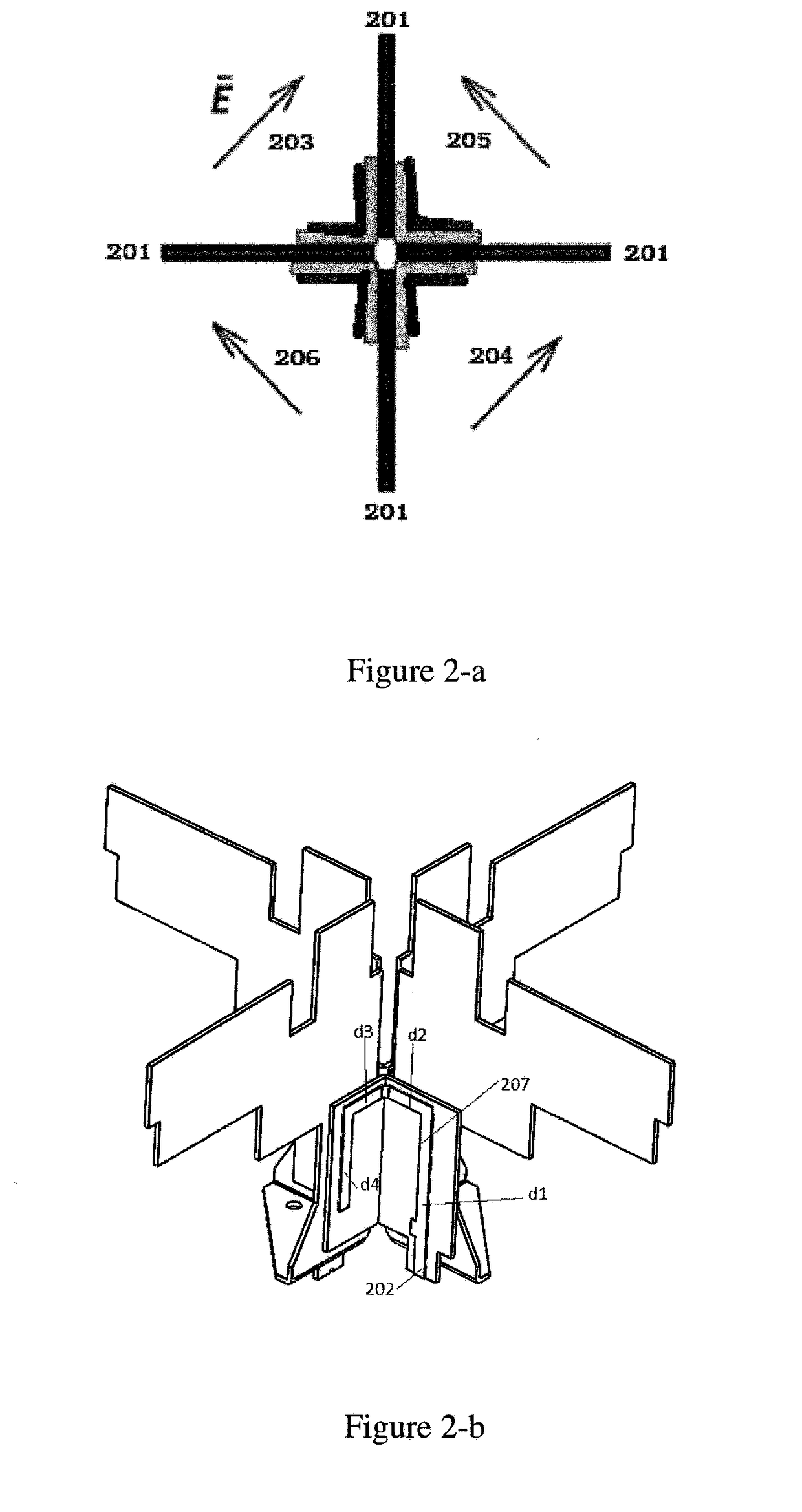
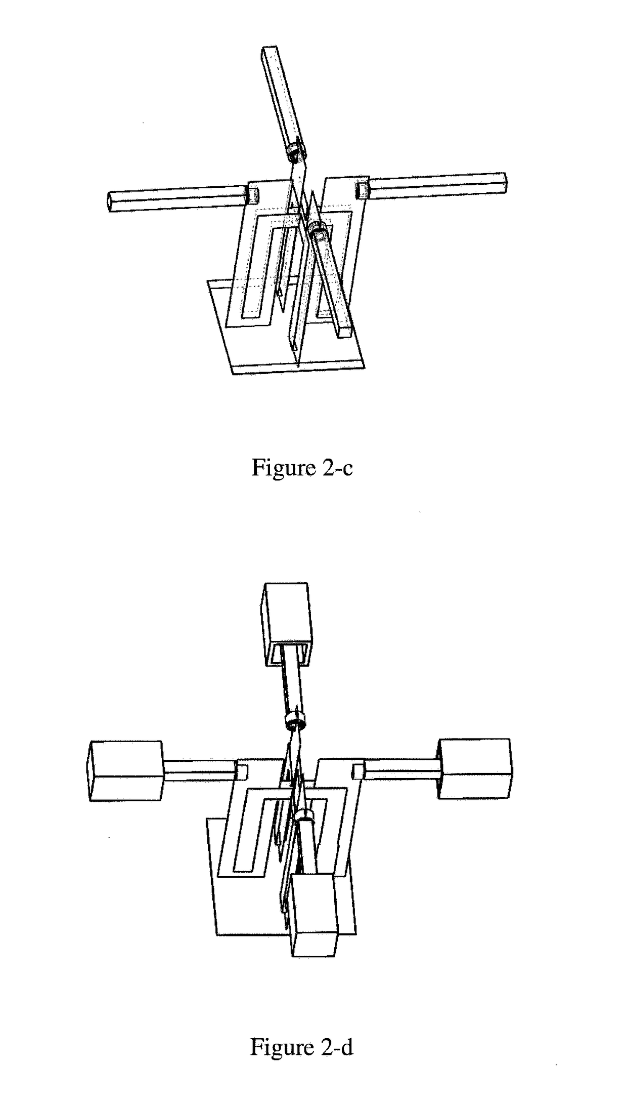
[0035]Before discussing the exemplary embodiments in more detail, it should be mentioned that the specific structural and functional details disclosed herein are merely illustrative and are for the purpose of describing the exemplary embodiments of the present disclosure. However, the disclosure may be embodied in many alternate forms and should not be construed as limited only to the embodiments set forth herein.

[0036]The terminology used herein is for the purpose of describing particular embodiments only and is not intended to limit exemplary embodiments. As used herein, the singular forms “a,”“an,” and “the” may be intended to include the plural forms as well, unless the context clearly indicates otherwise. It should also be understood that the terms “including” and / or “comprising” as used herein define the presence of stated features, integers, steps, operations, units and / or components without precluding the presence or addition of one or more other features, integers, steps, o...


PUM


Abstract

The present disclosure provides a low band dipole and a multi-band multi-port antenna arrangement, wherein the low band dipole has four dipole arms, and the four dipole arms are horizontally and mutually perpendicularly placed in a “+” shape and adjacent two mutually perpendicular dipole arms are fed therebetween. The antenna arrangement includes a main reflector, at least one column of low band dipole array disposed on the main reflector, and at least one column of high band dipole array adjacent to the at least one column of the low band dipole array, wherein at least one low band dipole in each column of the at least one column of low band dipole array satisfies the following condition: the low band dipole has four dipole arms, and the four dipole arms are horizontally and mutually perpendicularly placed in a “+” shape, and adjacent two mutually perpendicular dipole arms are fed therebetween to form a + / −45 degree polarization. The multi-band multi-port antenna arrangement solves the problem that the high and low band dipole arms shield each other and reduces the mutual coupling between the high and low band dipoles by adopting the above-mentioned structure of the low band dipole.

Description

TECHNICAL FIELD[0001]The present disclosure relates to the field of communication technologies, and in particular, to a low band dipole and a multi-band multi-port antenna arrangement including the low band dipole.BACKGROUND OF THE INVENTION[0002]Existing multi-band multi-port antenna arrangements are generally arranged in a nested manner, as shown in FIG. 1-a. The high band dipole is in the middle of the low band dipole. This kind of arrangement inevitably leads to great mutual coupling between the high- and low-band dipoles, which causes degraded standing wave of the high band dipole placed in the middle of the low band dipole, distorted pattern, and difficult debugging of the isolation indicator. The high band dipole placed at the periphery of the low band dipole is also significantly affected by the low band dipole arm, which has less influence on the standing wave and isolation, and has a greater influence on the pattern; the middle high band dipole also has an effect on the st...

Claims


Application Information

Patent Timeline
Patent Type & Authority Applications(United States)
IPC IPC(8): H01Q1/52H01Q9/44H01Q1/36H01Q21/24H01Q15/14
CPCH01Q1/521H01Q9/44H01Q1/36H01Q21/24H01Q15/14H01Q1/523H01Q1/246H01Q19/108H01Q21/08H01Q21/26H01Q21/28H01Q5/48H01Q9/28H01Q5/00
Inventor SEMONOV, KOSTYANTYNXU, CHENGYULI, YAOHUAN
Owner RFS TECH INC
Why Eureka
Try Eureka