Disc Brake For A Motor Vehicle and Brake Pad Assembly Therefor

Active Publication Date: 2018-12-13
LUCAS AUTOMOTIVE GMBH
View PDF6 Cites 0 Cited by
  • Summary
  • Abstract
  • Description
  • Claims
  • Application Information

AI Technical Summary

Benefits of technology

The patent describes a reset device for disc brakes that can improve performance and prevent excessive wear on brake pads. The device has two regions: an elastically deformable region and a plastically deformable region. The elastic region allows for better separation of reset and wear compensation, while the plastic region prevents wear and ensures proper functioning. The device is made of sheet metal and has a compact structure, which makes it easier to install and maintain. The device can be produced and maintained more quickly and easily by using a common, one-piece basic body and additional attachment extensions. Overall, the patent describes a solution that can improve the performance and longevity of braking systems.

Problems solved by technology

In systems of this kind with elastic and plastic deformation of one and the same region, impairment of the resetting of the brake pads can occur in particular in the case of heavy wear that is to be compensated for.

Method used


Image

  • Disc Brake For A Motor Vehicle and Brake Pad Assembly Therefor
  • Disc Brake For A Motor Vehicle and Brake Pad Assembly Therefor
  • Disc Brake For A Motor Vehicle and Brake Pad Assembly Therefor

Examples


exemplary embodiment 1

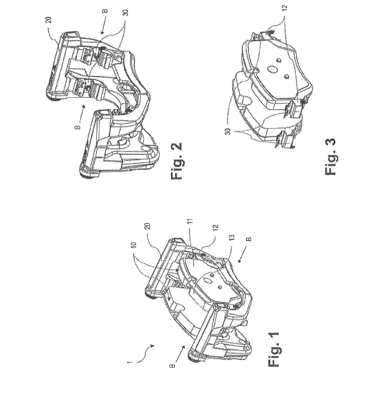
[0041]FIG. 1 shows a disc brake 1 according to the invention for a motor vehicle. Here two opposing brake pad assemblies 10 are to be recognized, which are constructed from a brake pad carrier 11 with lateral retaining tongues 12 and a vehicle brake pad 13. The brake pad assemblies 10 are facing one another on their vehicle brake pad side and are spaced from one another so that a brake disc, which is not shown, can be arranged in between and the vehicle brake pad 13 can be brought into interaction with the brake disc for achieving a braking effect in that the brake pad assemblies 10 are moved in an actuation direction B. This movement in the actuation direction B can be effected in a known manner via a hydraulic actuation mechanism, wherein the brake pad assemblies 10 are held by a brake carrier 20 and are guided movably in a braking manner in this by the retaining tongues 12.

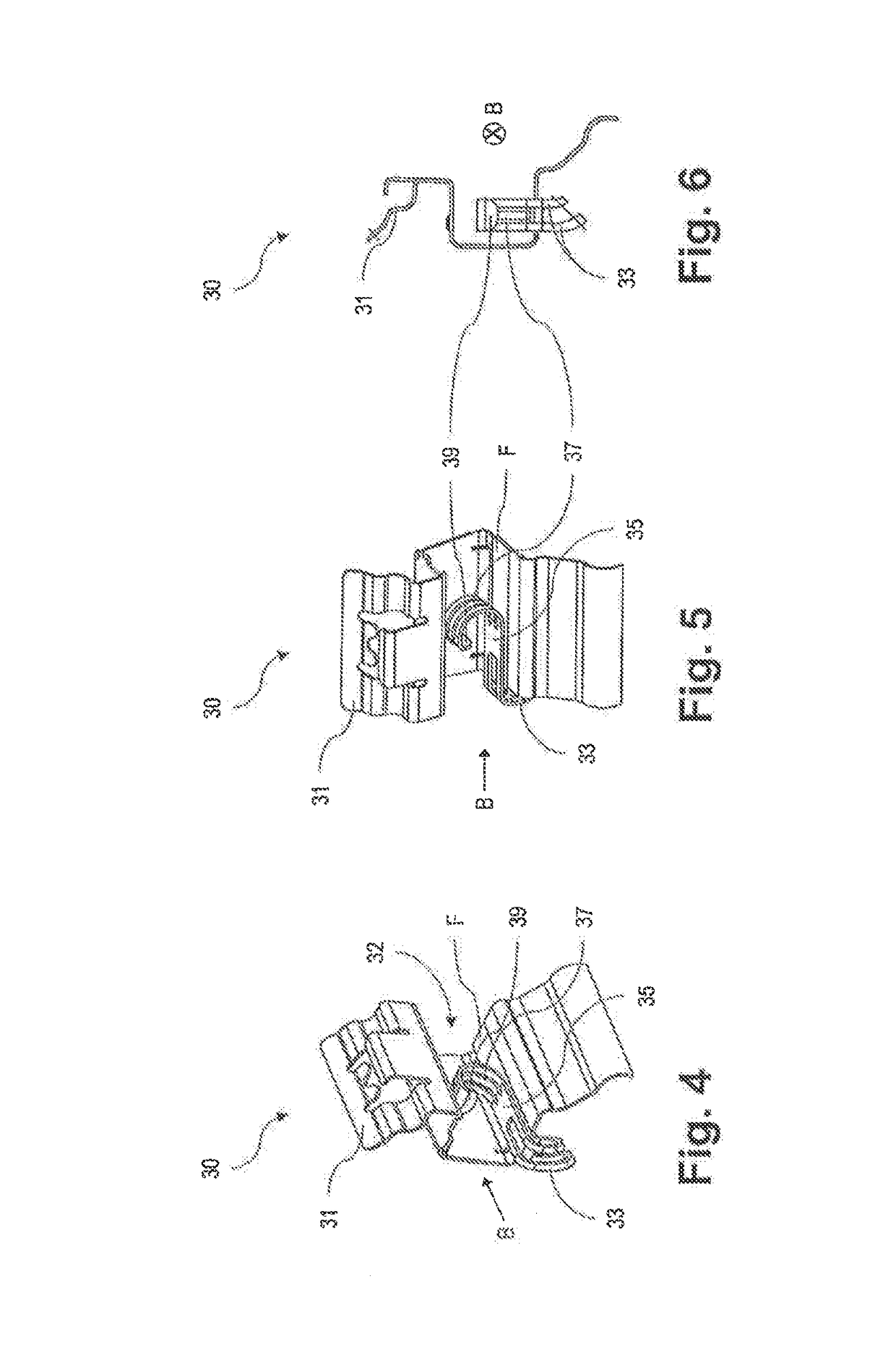
[0042]In FIG. 2 the brake pad assemblies 10 have been removed from the disc brake 1. Here guides 30 formed f...

exemplary embodiment 2

[0052]The second exemplary embodiment according to FIGS. 12 to 17 differs from the first exemplary embodiment in that the reset device has a stop 134, which is able to limit the spring path X of the elastically deformable region 133, so that each further movement of the retaining tongue 12 in the actuation direction B leads to a plastic deformation of the plastically deformable region 137.

[0053]In this context FIGS. 12 and 13 show the two states of the elastically deformable region 133.

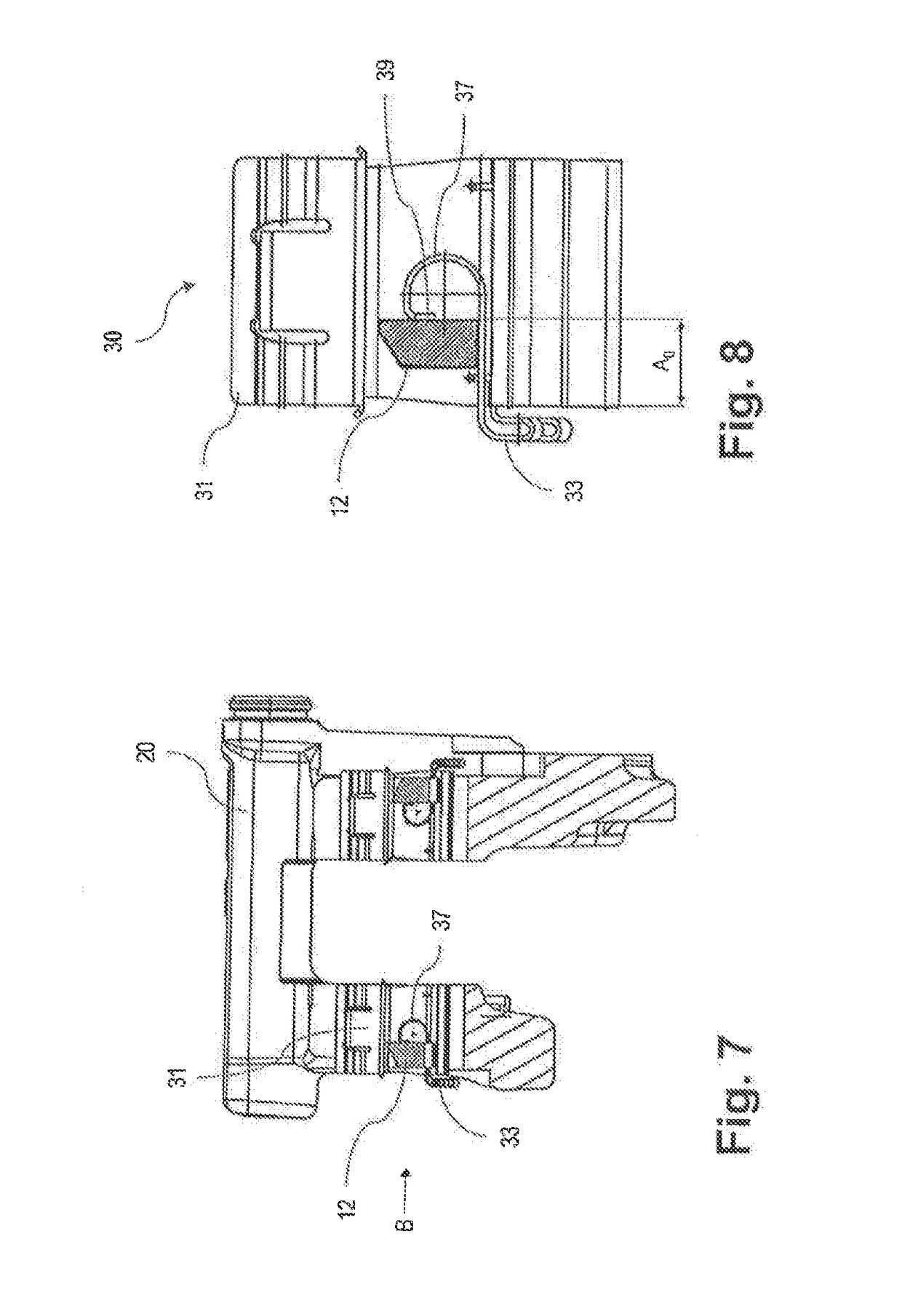
[0054]In FIG. 12 no elastic deformation has yet taken place, which is why the entire spring path X (>0) is available, which is measured from the inner face, oriented to the right in the figure, of the stop 134 to the opposite stop point. The guide distance in this resting position, which is measured parallel to the guide surface F from the left edge of the guide surface F, which faces the elastically deformable region 133, as far as the engagement point on the engagement lip 139, is designated by A0.

[...

exemplary embodiment 3

[0057]The third exemplary embodiment according to one of the FIGS. 18 to 21 differs from the second exemplary embodiment in that the reset device, in addition to a stop 234, has two elements M1, M2, which are formed separately but are actively connected to one another in the state shown, wherein one element M1 only has the plastically deformable region 237.

[0058]The reset device shown in FIG. 18 and in FIG. 19 as an enlarged view enables a transition region to be recognized between the elements M1 and M2, wherein the element M1 is hooked into the elastically deformable region 233 of the element M2 by means of a hook and rests on this in the actuation direction B, so that both on actuation and on reset of the brake pad assembly 10, compressive loading and no tensile loading, for example on the hook, prevails. While this exemplary embodiment provides a detachable connection between the elements M1 and M2, an undetachable connection, e.g. due to gluing, soldering or welding, can also b...


PUM


Abstract

A disc brake for a motor vehicle comprising a guide in which at least one brake pad assembly is guided such that it can move in a braking manner, wherein the brake pad assembly has a brake pad carrier on which a vehicle brake pad is attached which can be interacted with a brake disc in order to achieve a braking effect, wherein the brake pad carrier has at least one retaining tongue, wherein the guide has at least one receiving region and wherein the retaining tongue can be accommodated in the at least one receiving means by being guided in an actuation direction, wherein a reset device is in contact with the at least one retaining tongue, via which reset device a reset force acting against the actuation direction can be applied to same subsequent to an elastic deformation caused by braking deflection of the brake pad assembly, wherein the reset device has an elastically deformable region for resetting the brake pad carrier and a plastically deformable region or the permanent adaptation to a wearing of the vehicle brake pad. According to the invention, with this disc brake, the reset device can only be plastically deformed, as a result of a force acting thereon in the actuation direction along a guide surface of the receiving region, if the reset device has adopted a predetermined, exclusively elastic deformation as a result of this force, wherein the plastically deformable region is formed as a loop and is in direct contact with the retaining tongue and can also roll out along the guide surface during the plastic deformation.

Description

CROSS-REFERENCE TO RELATED APPLICATIONS[0001]This application is a national stage of International Application No. PCT / EP2016 / 062874, filed 7 Jun. 2016, the disclosures of which are incorporated herein by reference in entirety, and which claimed priority to German Patent Application No. 10 2015 007 523.3, filed 12 Jun. 2015, the disclosures of which are incorporated herein by reference in entirety.BACKGROUND OF THE INVENTION[0002]The present invention relates to a disc brake for a motor vehicle and in particular to a disc brake comprising a guide, in which at least one brake pad assembly is guided movably in a braking manner, wherein the brake pad assembly comprises a brake pad carrier, to which a vehicle brake pad is attached, which can be brought into interaction with a brake disc for achieving a braking effect, wherein the brake pad carrier has at least one retaining tongue, wherein the guide has at least one receiving region and wherein the retaining tongue can be accommodated, ...

Claims


Application Information

Patent Timeline
IPC IPC(8): F16D65/097F16D65/00F16D65/22B60T1/06F16D65/54F16D55/226
CPCF16D65/0972F16D65/0068F16D65/22B60T1/065F16D65/543F16D65/0978F16D55/2262F16D2055/0029F16D2200/0004F16D2127/02F16D2129/04F16D65/0977
Inventor MALLMANN, MARKUS
Owner LUCAS AUTOMOTIVE GMBH
Why Eureka
Try Eureka