Thermionic Power Cell

a power cell and thermal energy technology, applied in the direction of generator/motor, electrical apparatus, radioation applications, etc., can solve the problems of large power generation, large rtg, large rtg, etc., and achieve the effect of reducing and increasing the cost of power supply

Active Publication Date: 2018-12-06
NASA
View PDF0 Cites 9 Cited by
  • Summary
  • Abstract
  • Description
  • Claims
  • Application Information

AI Technical Summary

Benefits of technology

[0005]A method for generating an electric current includes heating a layer of electron emitting material disposed on a layer of radioactive material by radioactive decay of the layer of radioactive material. The method includes emitting electrons from the layer of electron emitting material to a layer of electron collecting material by thermionic emission. The layer of electron emitting material is physically separated from the layer of electron collecting material to define a chamber between the layer of electron collecting material and the layer of electron emitting material. The chamber is substantially evacuated to permit electrons to traverse the chamber from the layer of electron emitting material to the layer of electron collecting material. The method includes inducing an electric current to flow through the layer of electron collecting material connected to an electrical load. Heat generated over time by the layer of radioactive material causes a substantially constant flow of electrons to be emitted by the layer of electron emitting material.

Problems solved by technology

RTGs are large, bulky, heavy, and costly and do not generate significant power, rendering RTGs unsuitable power supplies for smaller and / or portable electronic devices.

Method used


Image

  • Thermionic Power Cell
  • Thermionic Power Cell
  • Thermionic Power Cell

Examples


Embodiment Construction

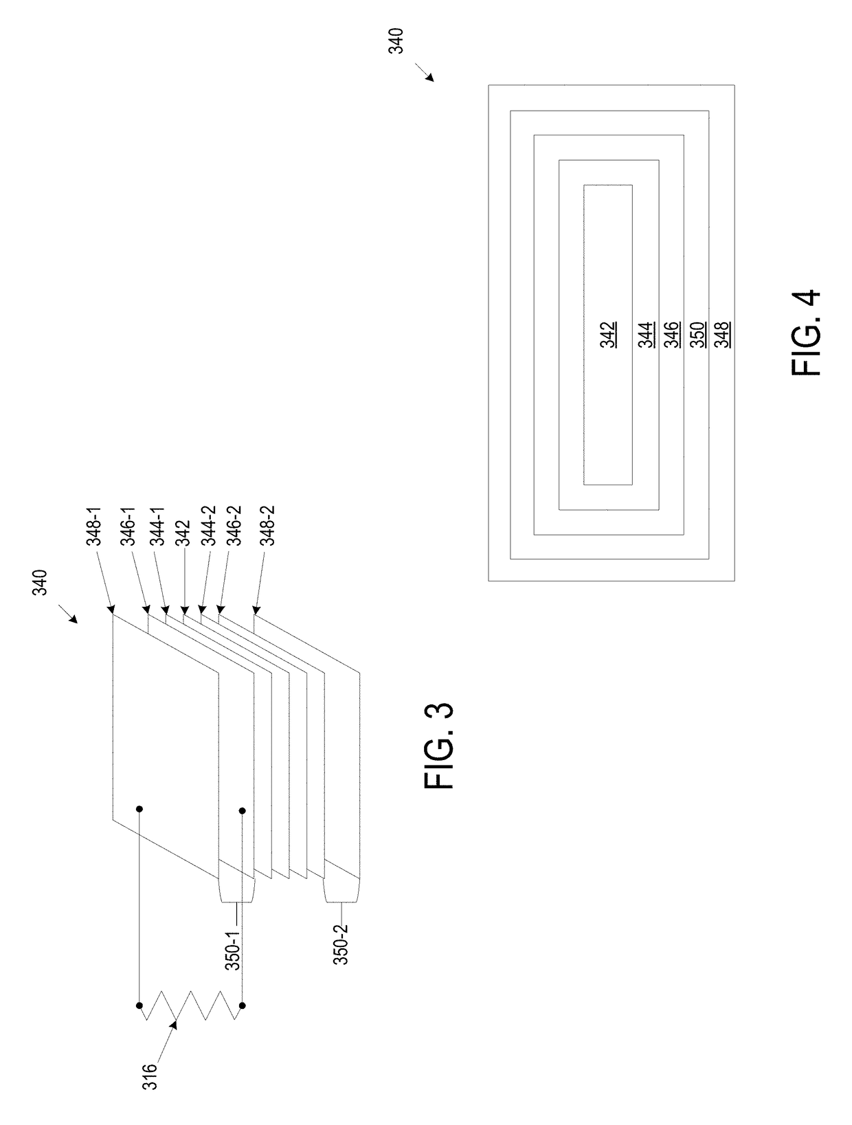
[0016]For purposes of description herein, the terms “upper,”“lower,”“right,”“left,”“rear,”“front,”“vertical,”“horizontal,” and derivatives thereof shall relate to the structure as oriented in FIG. 3. However, it is to be understood that the embodiments may assume various alternative orientations and step sequences, except where expressly specified to the contrary. It is also to be understood that the specific devices and processes illustrated in the attached drawings, and described in the following specification, are simply exemplary embodiments of the inventive concepts defined in the appended claims. Hence, specific dimensions and other physical characteristics relating to the embodiments disclosed herein are not to be considered as limiting, unless the claims expressly state otherwise.

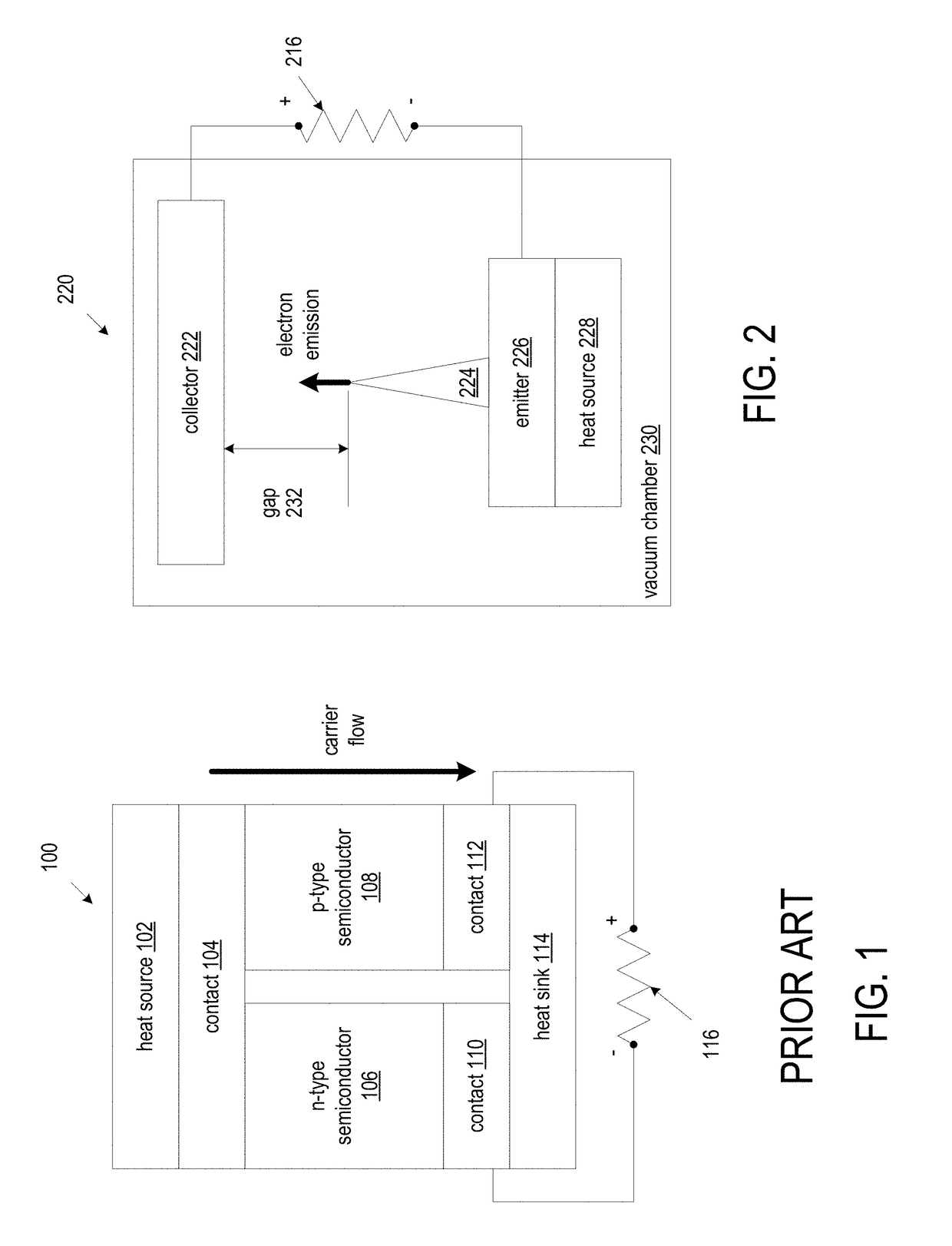
[0017]FIG. 1 is a block diagram schematic of an illustrative thermoelectric generator (TEG) 100 as known in the prior art. The illustrated TEG is a solid state device that converts heat flux directl...


PUM


Abstract

A thermionic (TI) power cell includes a heat source, such as a layer of radioactive material that generates heat due to radioactive decay, a layer of electron emitting material disposed on the layer of radioactive material, and a layer of electron collecting material. The layer of electron emitting material is physically separated from the layer of electron collecting material to define a chamber between the layer of electron collecting material and the layer of electron emitting material. The chamber is substantially evacuated to permit electrons to traverse the chamber from the layer of electron emitting material to the layer of electron collecting material. Heat generated over time by the layer of radioactive material causes a substantially constant flow of electrons to be emitted by the layer of electron emitting material to induce an electric current to flow through the layer of electron collecting material when connected to an electrical load.

Description

CROSS-REFERENCE TO RELATED PATENT APPLICATION(S)[0001]This patent application claims the benefit of priority to U.S. Provisional Application No. 62 / 513,497, filed on Jun. 1, 2017, the contents of which are hereby incorporated by reference in their entirety for any purpose whatsoever.STATEMENT REGARDING FEDERALLY SPONSORED RESEARCH OR DEVELOPMENT[0002]The invention described herein was made in the performance of work under a NASA contract and by an employee of the United States Government and is subject to the provisions of Public Law 96-517 (35 U.S.C. § 202) and may be manufactured and used by or for the Government for governmental purposes without the payment of any royalties thereon or therefore. In accordance with 35 U.S.C. § 202, the contractor elected not to retain title.BACKGROUND[0003]Portable electronic devices require a power supply to function. The power supply may be internal to a device, such as a battery including electrochemical cells, or external to the tool, such as ...

Claims


Application Information

Patent Timeline
Patent Type & Authority Applications(United States)
IPC IPC(8): G21H1/00H02N11/00
CPCG21H1/00H02N11/002
Inventor CHOI, SANG H.DUZIK, ADAM J.
Owner NASA
Why Eureka
Try Eureka