Actuating devide and method of making the same
- Summary
- Abstract
- Description
- Claims
- Application Information
AI Technical Summary
Benefits of technology
Problems solved by technology
Method used
Image
Examples
first embodiment
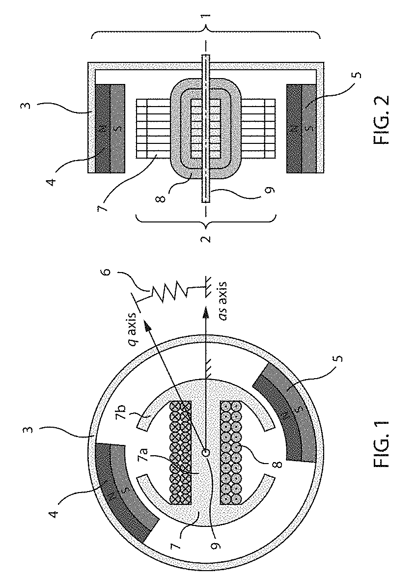
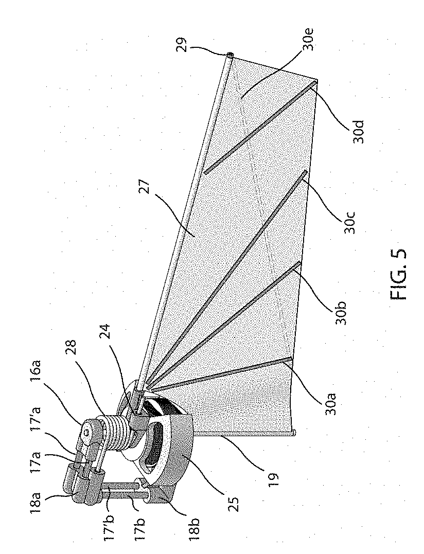
[0024]the actuator is shown in FIG. 5 and FIG. 6. This embodiment is optimized for a decagram scale flapping wing micro aerial vehicle. Specifically, the wing length is 70 mm long and flapping at 34 Hz. The single actuator / wing system in FIG. 5 weights 4.3 grams and generates a lift of 8.2 grams. The complete vehicle is shown in FIG. 7. The system has three main components, the actuator, wing and frame. The frame has two bearing housings 16, connected using lightweight carbon fiber rods 17 and two elbows 18a and 18b. A stainless-steel shaft 19 runs through the bearings 20 and a clearance-fit brass sleeve bearing 21 with in the stator core 22. The stator core and winding 23 are fixed to the lower bearing housing 16′. A wing adaptor 24 is mounted on the rotor housing 25 of the actuator. Two neodymium permanent magnets 26 are attached to the rotor housing. The rotor housing has an open design to accommodate the wing membrane 27, enables the actuator to sit compactly at wing shoulder. A...
second embodiment
[0025]the actuator is shown in FIG. 9. This embodiment is optimized for a sub-gram scale flapping wing micro aerial vehicle. Specifically, the wing length is 15 mm long and flapping at 160 Hz. The single actuator / wing system weights 0.24 grams and generates a lift of 0.45 grams. The two-wing vehicle is shown in FIG. 10. The outer diameter of the actuator is 6.8 mm but the parts are design with manufacturability in mind. The rotor housing 42 is reduced to a punched metal plate, where the two magnets 43 are attached within. The elastic element in this embodiment is a cantilevered leaf spring 44 with its end fixed on the rotor housing. The core 45 and coil 46 is mounted on the stator housing 47. The wing 48 is connected to the rotor through the wing adaptor 49. A miniature drive shaft 50 is fixed on the rotor and runs through the sleeve bearing 51 in the stator and 52 in the retainer 53. Two actuator can be connected using carbon fiber rods 54. A PCB body 55 with a miniature H-bridge d...
third embodiment
[0026]The third embodiment is designed for underwater vehicles, shown in FIG. 12. The fin is 100 mm long and flapping at 7 Hz. The Actuator has a diameter of 44 mm, weights 85 grams and produces a propulsion of 5.9N. For underwater vehicle, there is no weight constraint. The geometry of the actuator is designed for maximum efficiency. The rotor housing 62 has a closed design. The magnets 63 are also thicker and almost connects with each other. The stator core 64 has almost fully connected core shoes only leaving a small airgap for winding coil 65. The stator is mounted on the base 66, which has a hollow tube throughout the stator. The top of the tube is threaded, a bearing housing 67 is screwed on to secure the stator and a ball bearing 68a sit in. Another ball bearing 68b is attached at the bottom of the base. A torsion spring 69 is directly attached to the core through a small hole around the bearing housing. The other end of the spring is connected to the rotor. The shaft 70 is h...
PUM
 Abstract
Description
Claims
Application Information
 - R&D
- Intellectual Property
- Life Sciences
- Materials
- Tech Scout
- Unparalleled Data Quality
- Higher Quality Content
- 60% Fewer Hallucinations
Browse by: Latest US Patents, China's latest patents, Technical Efficacy Thesaurus, Application Domain, Technology Topic, Popular Technical Reports.
© 2025 PatSnap. All rights reserved.Legal|Privacy policy|Modern Slavery Act Transparency Statement|Sitemap|About US| Contact US: help@patsnap.com


