Transport system, carriage, positioning apparatus, processing system, and positioning method

Active Publication Date: 2018-11-22
CANON KK
View PDF0 Cites 2 Cited by
  • Summary
  • Abstract
  • Description
  • Claims
  • Application Information

AI Technical Summary

Benefits of technology

The present invention provides a transport system, carriage, positioning apparatus, and positioning method that can accurately and stably position a work on the carriage while reducing its weight and size.

Problems solved by technology

When a work is passed from the transport apparatus to the positioning apparatus and the work is positioned for each working process as described above, there is a concern of dead time caused by the time required for passing and the time required for positioning.
Furthermore, there is a concern of a flaw in a work caused by multiple times of repetition of work handling.
In this case, however, with a plurality of pushers and actuators for pusher operations being mounted on the transport carriage, there is a problem of increased size and complexity of the transport carriage.
Thus, while it is necessary to firmly fix a work on the transport carriage, this requires larger pushing force of a pusher, which results in a concern that a flaw or the like is caused in the work when positioned.
Further, with the actuator for a pusher operation being provided on the transport carriage, this leads to a problem of a limited operation area of the transport carriage due to cables, pipes, or the like used for transmitting motive power to the actuator.
Thus, in the art disclosed in Japanese Patent No. 4014183, there are problems of increased size and complexity of the transport carriage and a limited movable area of the transport carriage.
Thus, in Japanese Patent Application Laid-Open No. 2003-145362, there are problems that, because a clamp hole is required to be formed in a work, a processed work is limited to a work in which a clamp hole can be formed, and that the positioning accuracy is lower than that in the contact positioning scheme.

Method used


Image

  • Transport system, carriage, positioning apparatus, processing system, and positioning method
  • Transport system, carriage, positioning apparatus, processing system, and positioning method
  • Transport system, carriage, positioning apparatus, processing system, and positioning method

Examples


first embodiment

[0042]A first embodiment of the present invention will be described with reference to the drawings.

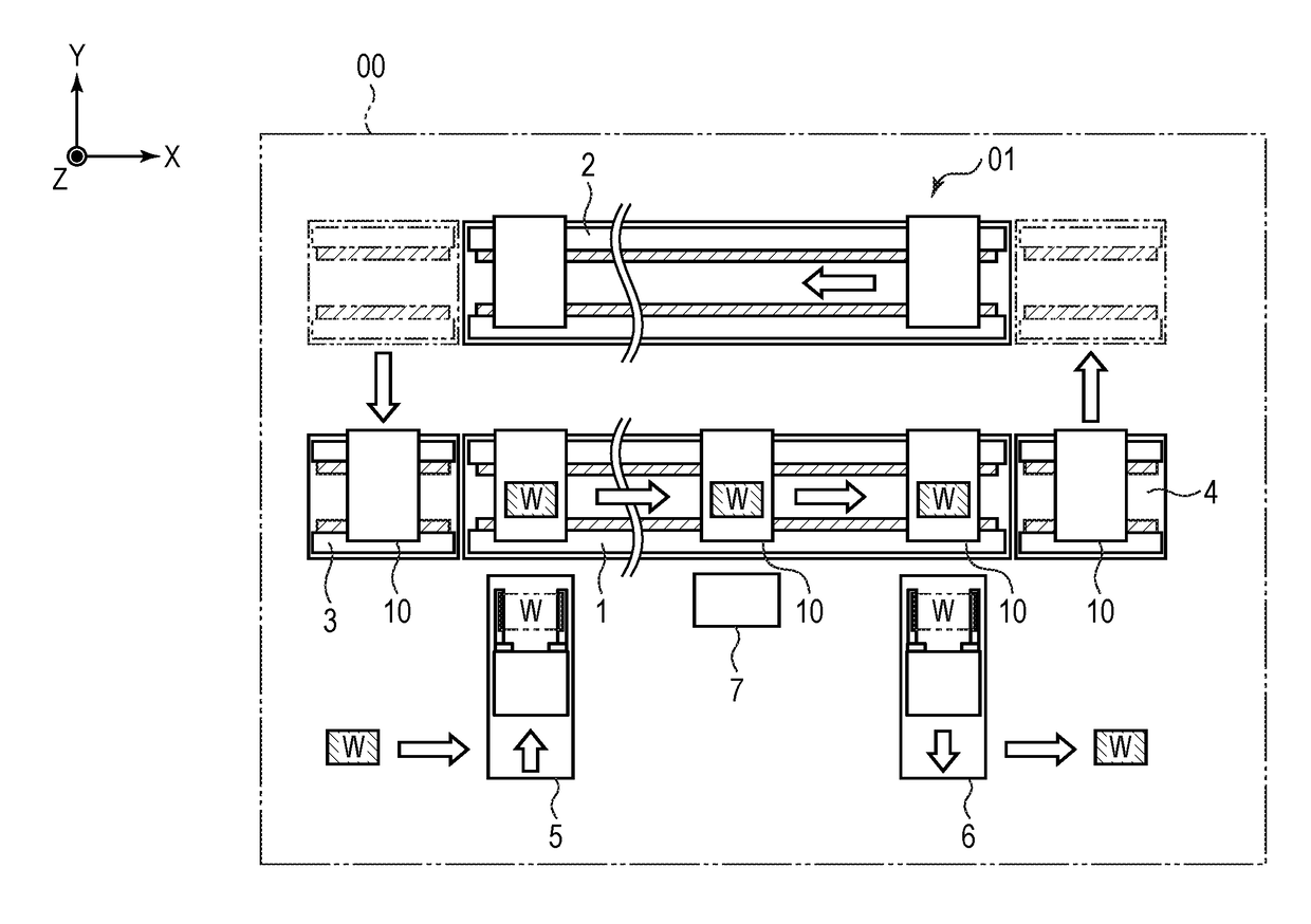
[0043]First, the entire configuration of a processing system of the present embodiment will be described by using FIG. 1. FIG. 1 is a schematic diagram illustrating the entire configuration of a processing system according to the present embodiment and schematically depicts a diagram of the entire system when viewed from the top.

[0044]As illustrated in FIG. 1, a processing system 00 according to the present embodiment has a transport apparatus forward path 1, a transport apparatus reverse path 2, a carriage transfer apparatus 3, a carriage transfer apparatus 4, a work input apparatus 5, a work output apparatus 6, a processing apparatus 7, and transport carriages 10. Further, the processing system 00 according to the present embodiment has a work positioning apparatus 110 described later. The processing system 00 according to the present embodiment includes a transport system 01 that tr...

second embodiment

[0138]A second embodiment of the present invention will be described by using FIG. 10. FIG. 10 is a schematic diagram illustrating the configuration of a transport carriage and a positioning apparatus according to the present embodiment. Note that similar components to those of the first embodiment described above are labeled with the same references and the description thereof will be omitted or simplified.

[0139]In the present embodiment, as illustrated in FIG. 10, the transport carriage 10, which is a carriage, has the top plate 15, the contact reference 101, the fixing unit 105, the spring 107 provided for the fixing unit 105, and a support member 108. Note that, in FIG. 10, the gravity 601 applied to the work W is schematically illustrated by an arrow.

[0140]In the present embodiment, unlike the first embodiment, the contact reference 101, which is a reference member for positioning the work W, is provided on the upper face of the top plate 15. The work W input on the transport c...

third embodiment

[0157]A third embodiment of the present invention will be described by using FIG. 11. FIG. 11 is a schematic diagram illustrating the entire configuration of a processing system according to the present embodiment. Note that similar components to those of the first and second embodiments described above are labeled with the same references and the description thereof will be omitted or simplified.

[0158]As illustrated in FIG. 11, a processing system 03 according to the present embodiment has the transport carriages 10, the work positioning apparatus 610, the press control apparatuses 620, the work input apparatus 630, a circulation transport apparatus 700, and a work output apparatus 730. The press control apparatus 620 is installed to each of the work input apparatus 630, the work positioning apparatus 610, and the work output apparatus 730.

[0159]The circulation transport apparatus 700 is a transport apparatus that transports the transport carriage 10, which is a carriage, and the c...


PUM


Abstract

A carriage on which a work is supplied and which is transported by a transport path has a reference member that is a reference for positioning of the work and a fixing unit whose motion is controlled by a control unit provided outside the carriage and that fixes the work. A work which has been positioned in a first direction on the carriage and has not yet been fixed by the fixing unit is pressed in a second direction against the reference member by a positioning unit, in which the second direction intersects with the first direction, and the work is positioned on the carriage in the second direction.

Description

BACKGROUND OF THE INVENTIONField of the Invention[0001]The present invention relates to a transport system that transports a work; a carriage and a positioning apparatus used in the transport system; a processing system having the transport system; and a work positioning method.Description of the Related Art[0002]In a processing system having a transport device of a work, a plurality of operation apparatuses that perform predetermined working processes are installed at predetermined intervals, and work transport apparatuses are each arranged between these working processes. Further, after predetermined processing is applied to works at each working process, the works are successively transported to the subsequent working process by the transport apparatus.[0003]In a processing system, in order to apply precision processing such as assembly of components in each working process, it is necessary to position a work at a predetermined position in advance. Thus, in the conventional proce...

Claims


Application Information

Patent Timeline
IPC IPC(8): H02K7/14H02K41/02H02K33/02B23P19/04
CPCH02K7/14H02K41/02H02K33/02B23P19/04B23P19/001B23P21/004B65G47/8838
Inventor OKAZAKI, RYOTAHIROKAWA, KICHINOSUKE
Owner CANON KK
Why Eureka
Try Eureka