
Fabrication of ultraviolet light emitting diode with tunnel junction

a technology of light-emitting diodes and tunnel junctions, which is applied in the direction of basic electric elements, electrical apparatus, and semiconductor devices, etc., can solve the problems of inability to use optical point sources, inefficient, and large, and achieve the effect of improving the efficiency of light-emitting diodes

Inactive Publication Date: 2018-11-15
X DEV LLC
View PDF3 Cites 9 Cited by
  • Summary
  • Abstract
  • Description
  • Claims
  • Application Information

AI Technical Summary

Benefits of technology

This patent describes a method for making an ultraviolet light emitting diode with a tunnel junction. The technical effects of this patent include providing a more efficient and compact UV source that can be used in various applications, such as extreme UV lithography and medical imaging. The method also allows for better control of the growth conditions of the tunnel junction, resulting in improved performance and reliability of the UV source.

Problems solved by technology

However, many of these UV sources may suffer from the same deficiencies as conventional light bulbs: they are large, inefficient, fragile, and cannot be used as optical point sources.

Method used


Image

  • Fabrication of ultraviolet light emitting diode with tunnel junction
  • Fabrication of ultraviolet light emitting diode with tunnel junction
  • Fabrication of ultraviolet light emitting diode with tunnel junction

Examples


Embodiment Construction

[0018]Embodiments of fabrication for an ultraviolet light emitting diode with a tunnel junction are described herein. In the following description numerous specific details are set forth to provide a thorough understanding of the embodiments. One skilled in the relevant art will recognize, however, that the techniques described herein can be practiced without one or more of the specific details, or with other methods, components, materials, etc. In other instances, well-known structures, materials, or operations are not shown or described in detail to avoid obscuring certain aspects.

[0019]Reference throughout this specification to “one embodiment” or “an embodiment” means that a particular feature, structure, or characteristic described in connection with the embodiment is included in at least one embodiment of the present invention. Thus, the appearances of the phrases “in one embodiment” or “in an embodiment” in various places throughout this specification are not necessarily all ...


PUM


Abstract

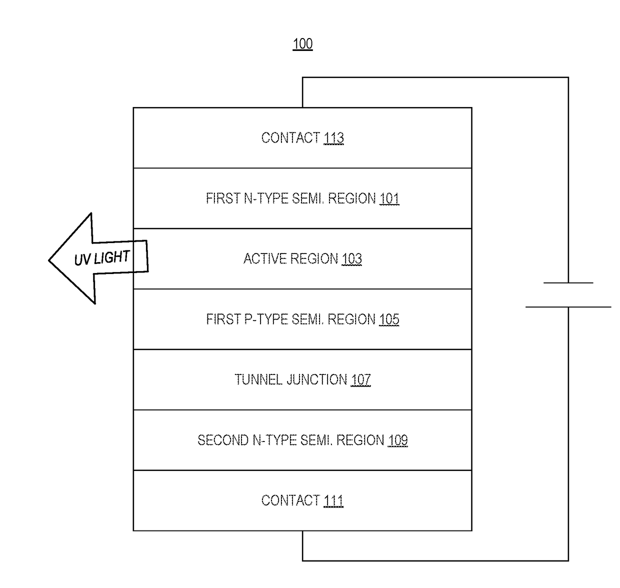
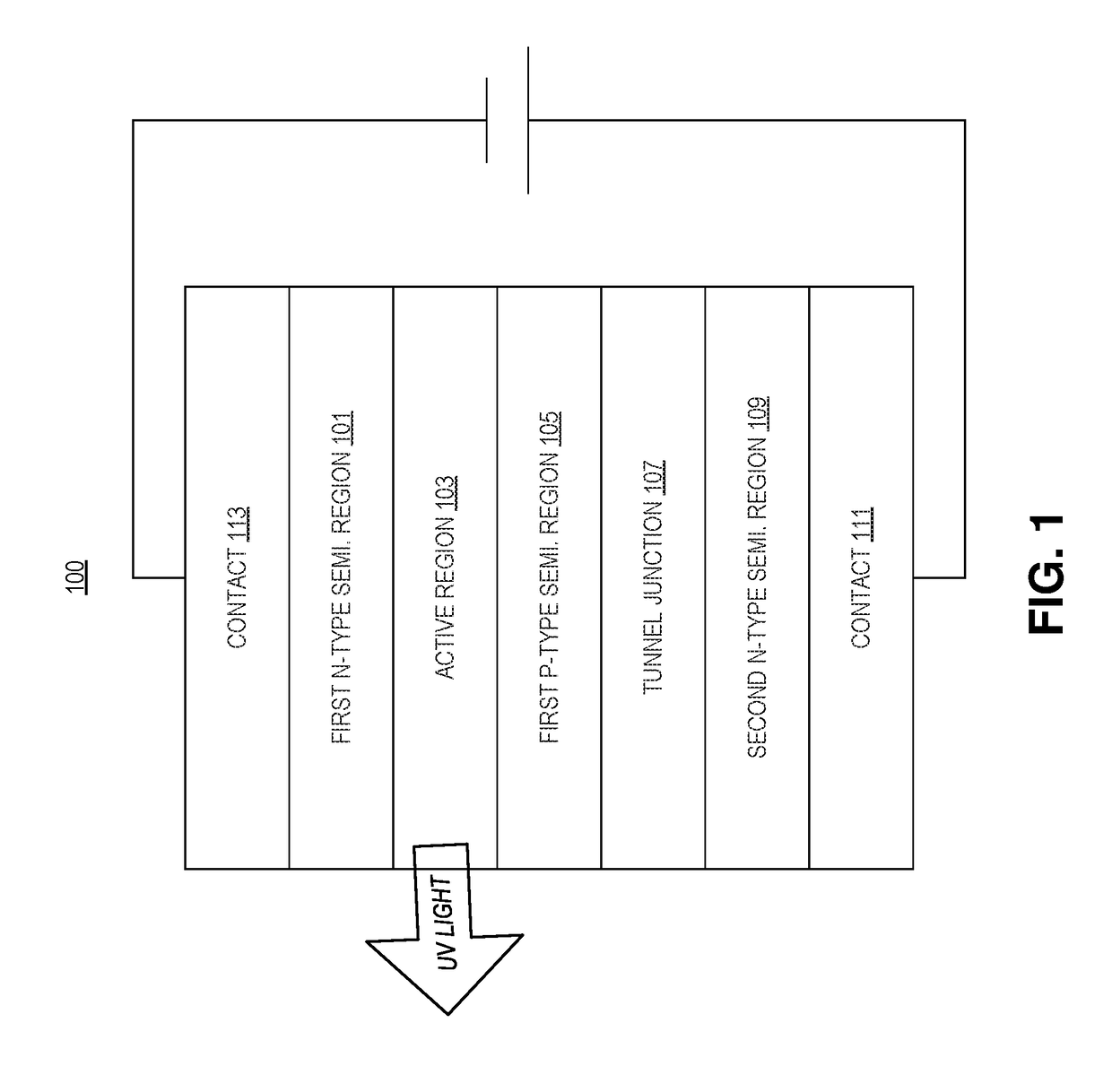
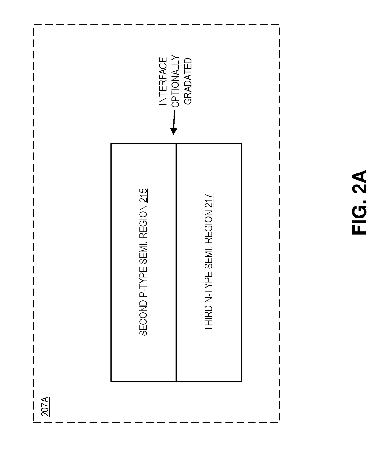
A method of fabricating a light emitting diode (LED) includes forming an active region structured to emit ultraviolet (UV) light and disposed between a first n-type semiconductor region and a first p-type semiconductor region. The method also includes forming a tunnel junction, where the first p-type semiconductor region is disposed between the active region and the tunnel junction, and where the tunnel junction is electrically coupled to inject charge carriers into the active region through the first p-type semiconductor region. A second n-type semiconductor region is also formed, where the tunnel junction is disposed between the second n-type semiconductor region and the first p-type semiconductor region.

Description

CROSS-REFERENCE TO RELATED APPLICATIONS[0001]This application claims the benefit of U.S. Provisional Application No. 62 / 505,717, filed May 12, 2017, the contents of which are incorporated herein by reference.TECHNICAL FIELD[0002]This disclosure relates generally to light emitting diodes.BACKGROUND INFORMATION[0003]Ultraviolet (UV) light loosely refers to electromagnetic radiation with a wavelength of 10 nm to 420 nm, this wavelength range is shorter than that of visible light but longer than X-rays. UV light is emitted from the sun and is approximately 10% of the sun's total output. Light in the UV spectrum can cause chemical reactions in organic molecules; accordingly UV light can cause significant biological effect (most notably sun burn).[0004]Due to UV light's ability to induce chemical reaction and cause materials to fluoresce, UV radiation has a number of applications. For example, light in the ˜10 nm wavelength range may be used for extreme UV lithography, light in the 230-26...

Claims


Application Information

Patent Timeline
IPC IPC(8): H01L33/06H01L33/40H01L33/22H01L33/32H01L33/00
CPCH01L33/06H01L33/405H01L33/22H01L33/325H01L33/0025H01L33/0075H01L33/04
Inventor GRUNDMANN, MICHAELSCHUBERT, MARTIN F.
Owner X DEV LLC
Learn More