
Apparatus and method for energy safety management

a technology of energy safety management and apparatus, applied in the field of apparatus and a method for energy safety management, can solve the problems of electrical fire, flammable material surrounding may be ignited, and heat generation

Active Publication Date: 2018-11-15
ELECTRONICS & TELECOMM RES INST
View PDF5 Cites 4 Cited by
  • Summary
  • Abstract
  • Description
  • Claims
  • Application Information

AI Technical Summary

Benefits of technology

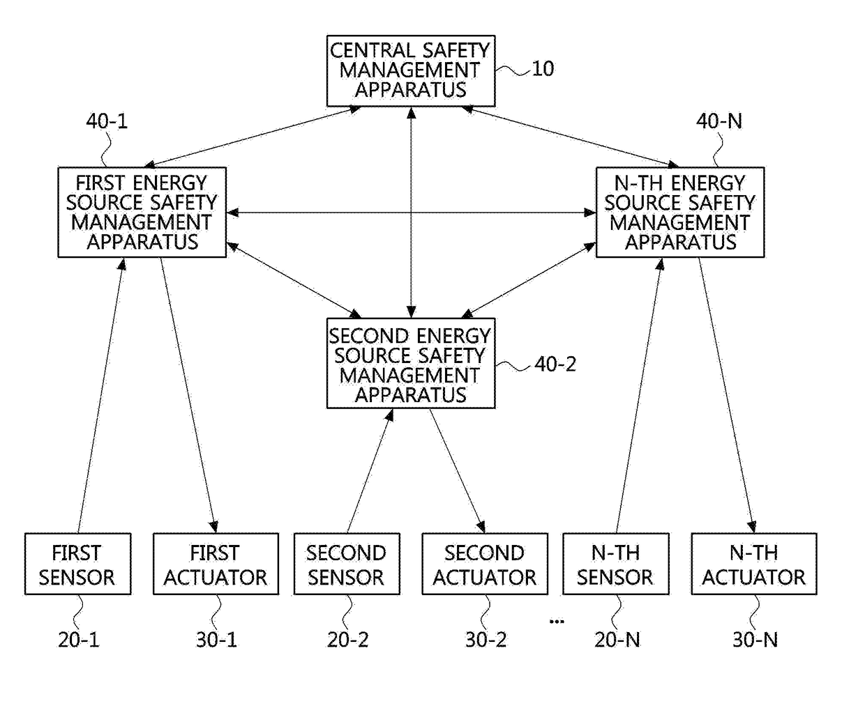
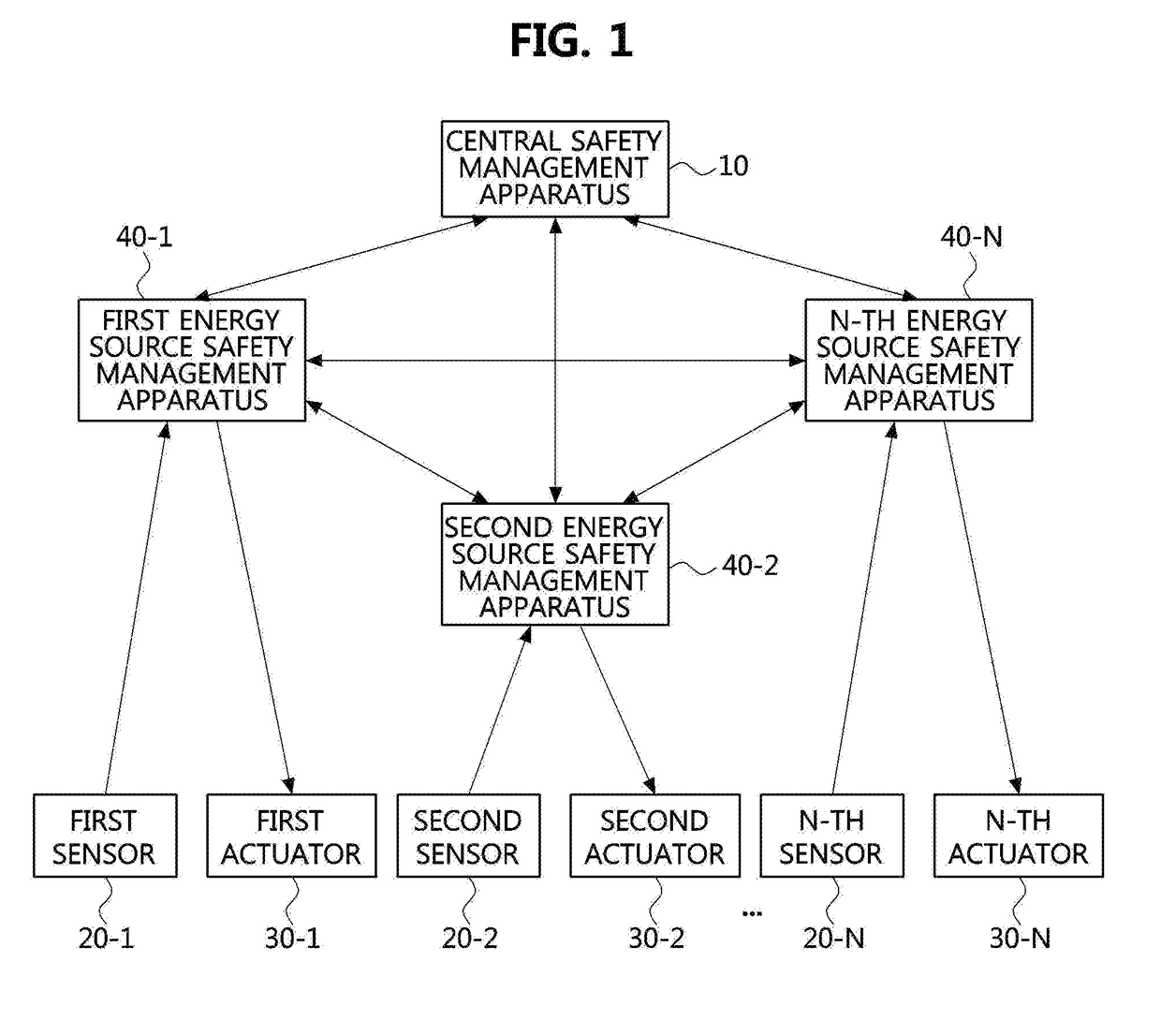
The present invention aims to provide a safety management system that can quickly cope with imminent safety accidents by exchanging information between energy source safety management apparatuses and the central safety management apparatus. This prompter response helps to prevent accidents and minimize damage caused by accidents. Additionally, the safety management system can quickly respond to safety management issues and provide a safety management report after pre-treatment.

Problems solved by technology

However, electricity is a serious factor that accounts for 30% of the total fire, and, may cause electrical fires by acting as an ignition source such as short circuit, overload, contact failure, electric leakage, electric spark, or the like.
The short circuit may occur when an insulator is destroyed or deteriorated, and a spark may be generated according to the short circuit, so that surrounding flammable material may be ignited.
Also, when the overload occurs, an excessive current may flow through an electric wire, heat may be generated, the coating of the electric wire may be damaged in succession, and an arc may be generated to cause an electrical fire.
Such the overload may be mainly caused by cable aging or increase in load capacity.
The increase in load capacity may generate heat, and an electrical fire may follow the same process as overloading.
The increase in load capacity may be attributed to insertion of too many pugs into an outlet at once.
The electric leakage is a phenomenon in which a current flows in a place other than a conductor, and an electrical fire may occur when a combustible object exists in the current path.
Such the leakage may also be caused by deterioration of the insulator.
Also, an electric spark may occur when a switch is opened or closed, and a fire may occur if such an electric spark touches the ignitable material.
Also, the electric spark may occur when a switch is opened or closed, and an electrical fire may occur if such the electric spark touches the flammable material.
Currently, earth leakage breakers of most houses have only functions of preventing electric shocks, but they do not have functions to prevent the electrical fires.
Therefore, leakage break by individual facilities are required.
In an environment where electric equipment and gas equipment are installed together, the ignition source of explosion may be a spark of electricity which causes gas explosion when gas is leaked.
Also, if an electrical disaster occurs, it may lead to additional gas disasters, and secondary disasters caused by the gas may lead to greater disasters.
However, in the past, each energy source has been independently managed without considering this.
However, since most safety accidents are imminent, there may be cases where the above-described series of processes are inappropriate to cope with the safety accidents.

Method used


Image

  • Apparatus and method for energy safety management
  • Apparatus and method for energy safety management
  • Apparatus and method for energy safety management

Examples


Embodiment Construction

[0045]Embodiments of the present disclosure are disclosed herein. However, specific structural and functional details disclosed herein are merely representative for purposes of describing embodiments of the present disclosure, however, embodiments of the present disclosure may be embodied in many alternate forms and should not be construed as limited to embodiments of the present disclosure set forth herein.

[0046]Accordingly, while the present disclosure is susceptible to various modifications and alternative forms, specific embodiments thereof are shown by way of example in the drawings and will herein be described in detail. It should be understood, however, that there is no intent to limit the present disclosure to the particular forms disclosed, but on the contrary, the present disclosure is to cover all modifications, equivalents, and alternatives falling within the spirit and scope of the present disclosure. Like numbers refer to like elements throughout the description of the...


PUM


Abstract

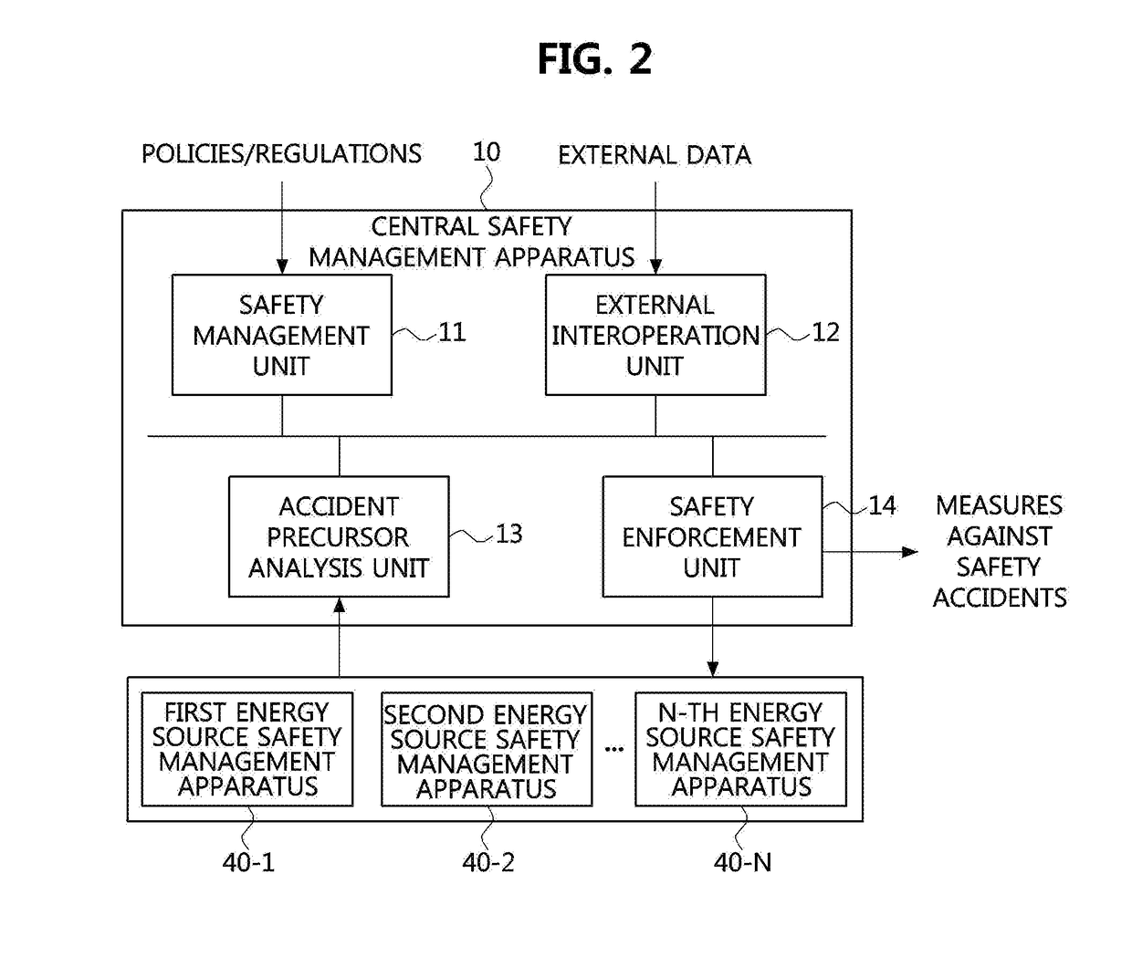
A central safety management apparatus includes a safety management unit collecting safety management policies and regulations for each energy source and calculating operation criteria for each energy source; an accident precursor analysis unit collecting accident event related information of each energy source from a plurality of energy source safety management apparatuses managing different energy sources and analyzing occurrence possibility of safety accidents in advance based on the accident event related information and the operation criteria; and a safety enforcement unit transmitting a result of the analysis of the accident precursor analysis unit to the plurality of energy source safety management apparatuses.

Description

CROSS-REFERENCE TO RELATED APPLICATION(S)[0001]This application claims priority to Korean Patent Application No. 10-2017-0058594, filed on May 11, 2017 in the Korean Intellectual Property Office (KIPO), the entire content of which is hereby incorporated by reference.BACKGROUND1. Technical Field[0002]The present disclosure relates to an apparatus and a method for energy safety management, and more specifically, to an apparatus and a method for energy safety management which prevent fusion safety accidents of different energy sources as well as safety accidents of a single energy source.2. Description of Related Art[0003]In our life, electric energy is used for the convenience of modern society because it is relatively easy to be converted to other forms of energy. However, electricity is a serious factor that accounts for 30% of the total fire, and, may cause electrical fires by acting as an ignition source such as short circuit, overload, contact failure, electric leakage, electric ...

Claims


Application Information

Patent Timeline
Patent Type & Authority Applications(United States)
IPC IPC(8): G05B19/042
CPCG05B19/042G05B2219/2639G05B19/0428G06Q50/265G06Q10/04G06Q50/06
Inventor DOH, YOON MEELEE, EUN JU
Owner ELECTRONICS & TELECOMM RES INST
Learn More