
Alternating current electrospray manufacturing and products thereof

Active Publication Date: 2018-11-15
CORNELL UNIVERSITY
View PDF0 Cites 0 Cited by
  • Summary
  • Abstract
  • Description
  • Claims
  • Application Information

AI Technical Summary

Benefits of technology

The patent describes a process and system for generating plumes of fluid stock using electrospraying, which can produce materials with uniform distribution of inclusions. The process involves injecting a charged fluid stock into a high velocity gas stream, which breaks apart the droplets and reduces the number of inclusions in each droplet. The plume contains droplets with a low concentration of inclusions, resulting in good distribution and thin films or coatings. The process also allows for high throughput and high concentration of inclusion components. The patent also describes a scalable manufacturing process for creating new materials with tailored nanostructures. The system offers higher production rates, better control of dispersion, and more precise control of coating thickness.

Problems solved by technology

In particular, films and coatings suffer from poor performance characteristics due to lack of uniformity of the film or coating (e.g., due to variations in dispersion and / or concentration of inclusions / additives, variations in film / coating thickness, etc.).

Method used


Image

  • Alternating current electrospray manufacturing and products thereof
  • Alternating current electrospray manufacturing and products thereof
  • Alternating current electrospray manufacturing and products thereof

Examples


example 1

Alternating Current Electrospray.

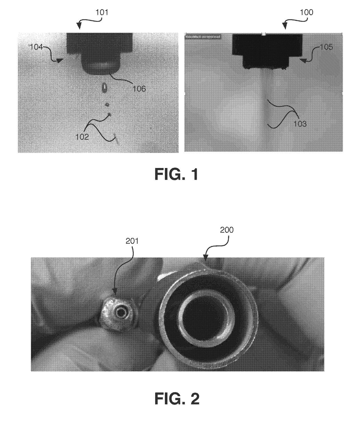
[0100]A fluid stock comprising 3 wt. % polyvinylalcohol (PVA) in water is prepared. The solution is provided (e.g., at a flow rate of about 0.01 to about 0.015 mL / min) to a non-gas-controlled electrospray nozzle, to which a direct voltage of about 10 kV to about 15 kV is maintained. A grounded collector is positioned opposite the electrospray nozzle, at a distance of about 20 cm to about 25 cm. High speed imaging of the electrospray process is illustrated in FIG. 1 (left panel, 101).

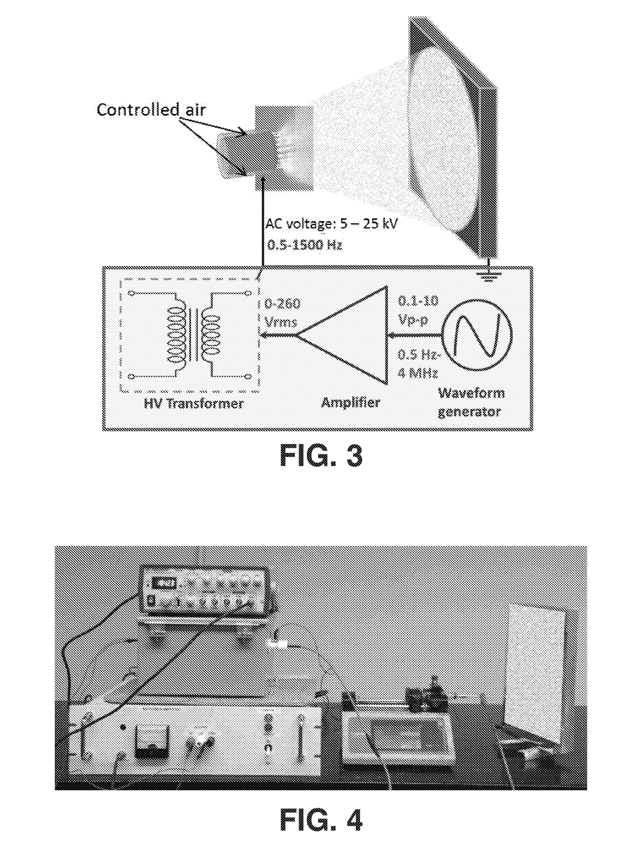
[0101]A similar 3 wt. % PVA (MW:78,000) solution is provided at a flow rate of 0.1 mL / min to a non-gas-controlled electrospray nozzle (the inner conduit being about 10 gauge), to which an alternating current (AC) voltage (VAC) of about 20 kV is applied at a frequency of about 100 to about 200. The collector / substrate is configured about 17 cm from the nozzle tip, with a coating deposited thereon.

[0102]A 7 wt. % PVA (MW:25,000) solution is provided at a flow rate of 0.1 mL...

example 2

Gas Controlled, Alternating Current Electrospray.

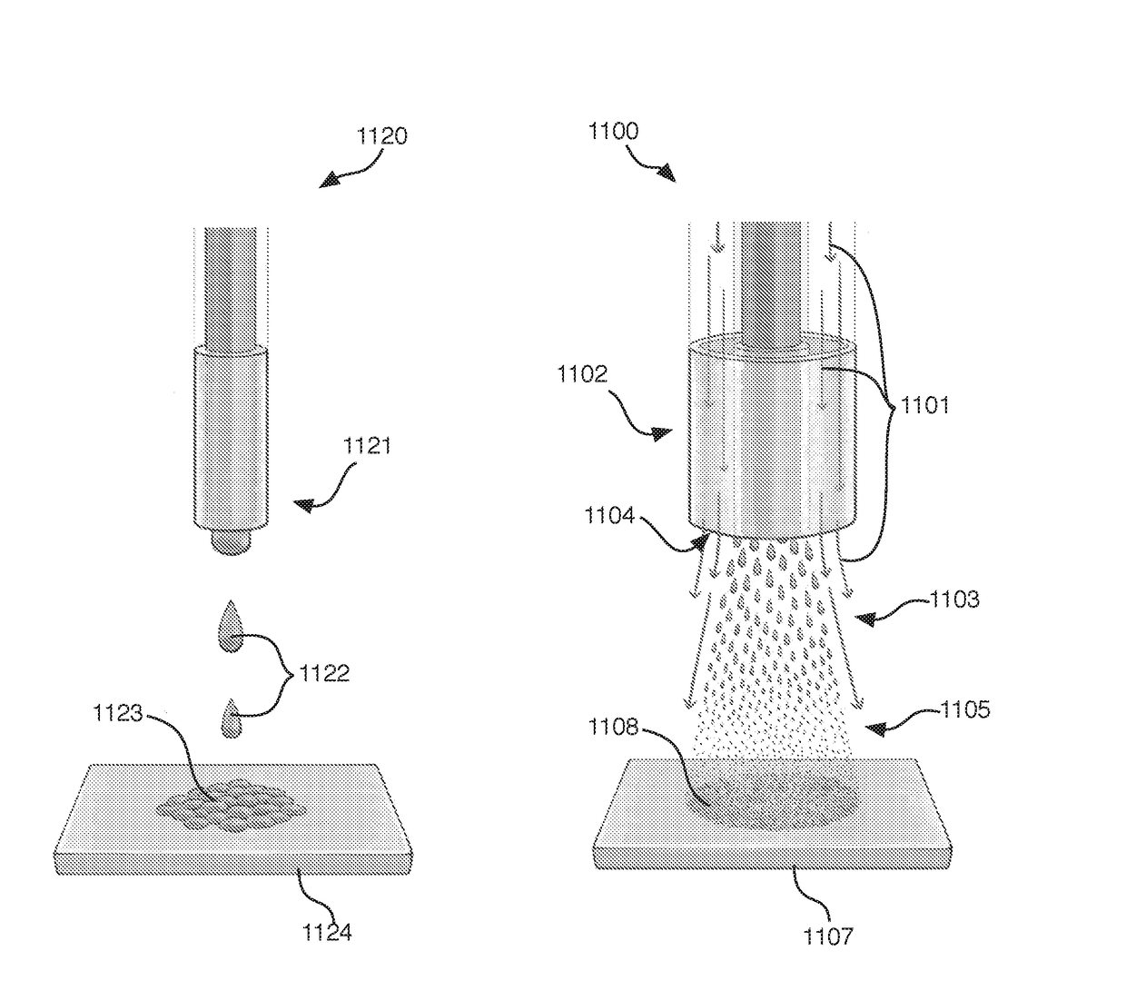
[0103]A PVA solution is prepared, such as set forth in Example 1. The fluid stock is electrosprayed by injecting the solution into a gas (air) stream using a coaxially configured nozzle as described herein. An alternating current (AC) voltage (Vac) is applied to the nozzle, and a coating is collected on a substrate a distance away from the nozzle. Exemplary parameters are illustrated in Table 1.

TABLE 1Exemplary gas controlled, alternating current electrospray parameters.ConcentrationNozzle SizeFrequencyVoltageFlow RateDistanceMW(wt. %)(gauge)(Hz)(kV)(mL / min)(cm)25,000316130200.1727516130200.1727716130200.62778,000316130200.3527

[0104]In addition, variation of air flow, voltage frequency, flow rate, etc. are observed to facilitate control of droplet breakup and coating formation. For example, FIG. 9 illustrates that in some instances, improved disruption of droplets is achieved when using high gas (e.g., air) pressure 920 (45 psi) compa...

example 3

[0106]Using fluid stocks and techniques, such as those described in Examples 1 and 2, a deposition is prepared by electrospraying the fluid stock using VAC and a nozzle having a diameter of up to 1 cm or more, such as illustrated in FIG. 2 (200).


PUM

PropertyMeasurementUnit
Lengthaaaaaaaaaa
Lengthaaaaaaaaaa
Lengthaaaaaaaaaa

Abstract

Provided in certain embodiments herein are alternating current electrospray systems and processes for manufacturing depositions, such as thin layer depositions. In some embodiments, processes and systems provided herein are suitable for and configured to manufacture uniform depositions, such as having uniform thickness.

Description

CROSS-REFERENCE[0001]This application claims the benefit of U.S. Provisional Application Nos. 62 / 254,405, filed Nov. 12, 2015, 62 / 254,392, filed Nov. 12, 2015, and 62 / 354,366, filed Jun. 24, 2016, each of which are incorporated herein by reference in their entireties.FIELD OF THE INVENTION[0002]The field relates films, coatings and depositions, particularly as prepared by electrospray techniques.BACKGROUND OF THE INVENTION[0003]Conventional electrospray is effective in creating small charged drops for ionization, atomization and aerosol applications, but inefficient at forming uniform and / or thin coatings and films, particularly at high throughput production rates.SUMMARY OF THE INVENTION[0004]Provided in certain embodiments herein are systems and processes for manufacturing depositions (e.g., films or coatings), such as thin layer depositions (e.g., films or coatings). In some embodiments, such systems and processes are configured to facilitate high throughput electrospraying using...

Claims


Application Information

Patent Timeline
IPC IPC(8): B05B5/03B05D1/06C09D129/04C09D7/61C09D7/40C09D7/20
CPCB05B5/03B05D1/06C09D129/04C09D7/61C09D7/67C09D7/20C08L101/00B05D3/042B05D1/04B05D2601/20B01J2/30C08J5/18Y10T428/30B82Y30/00B05D5/08
Inventor JOO, YONG LAKZHMAYEV, YEVGEN
Owner CORNELL UNIVERSITY
Learn More