
Optical Filter

a technology of optical filters and filters, applied in the field of night vision devices, can solve the problems of reducing affecting the user's situational awareness, and causing the user to be illuminated by the display of nvd, so as to reduce the time required for users' eyes to darken, and reduce the splashback

Inactive Publication Date: 2018-11-08
SPECTRUM TECH INT LTD
View PDF2 Cites 0 Cited by
  • Summary
  • Abstract
  • Description
  • Claims
  • Application Information

AI Technical Summary

Benefits of technology

The invention is a system that places a filter in the NVD eyepiece optics to avoid scratching, easy installation, and filter loss. This system uses specific optical filters that enhance night vision and significantly reduce the time needed for the user's eyes to dark adapt. The filters modify light emitted from the display so that it does not splash-back on the observer's face. This improves the ease and safety of using filtered NVD without degrading its performance.

Problems solved by technology

During this transition, the eye has difficulty detecting objects resulting in a condition called night blindness.
Termed facial signature or splash, this is very undesirable because it will disclose the presence and location of the NVD user to hostile persons who happen to be looking in the direction of the NVD user.
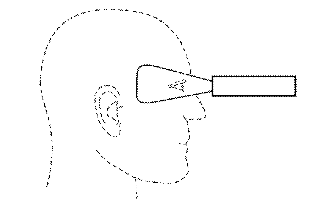
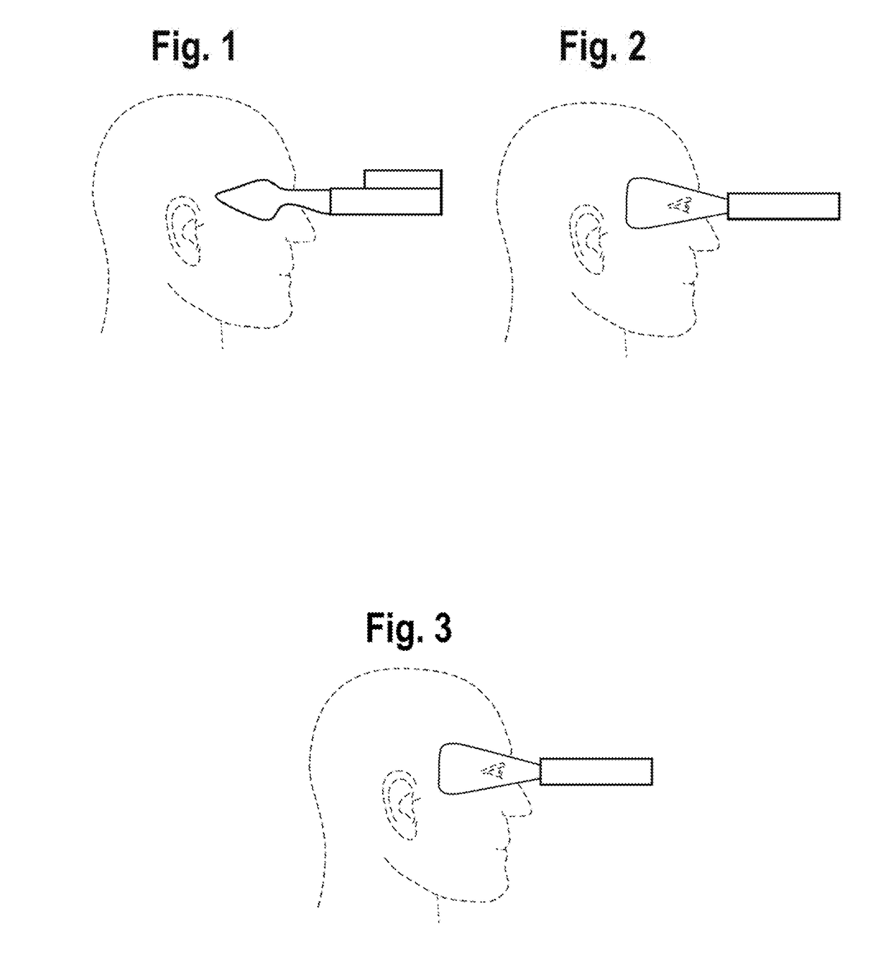
This existing design results in a portion of the face 4 being illuminated by the display of the NVD which is undesirable.
This result significantly and detrimentally compromises the user's situational awareness when using an NVD with such an eyecup.
This is undesirable.
While this succeeds in a major objective as described above, placement of the filter in this location subjects the filter to scratching, difficulty of field installation and outright loss of the filter.

Method used


Image

  • Optical Filter
  • Optical Filter
  • Optical Filter

Examples


Embodiment Construction

[0024]While the invention will be described in connection with a preferred embodiment, it will be understood that it is not intended to limit the invention to this embodiment. On the contrary, it is intended to cover all alternatives, modifications and equivalents as may be included within the spirit and scope of the invention as defined by the appended claims.

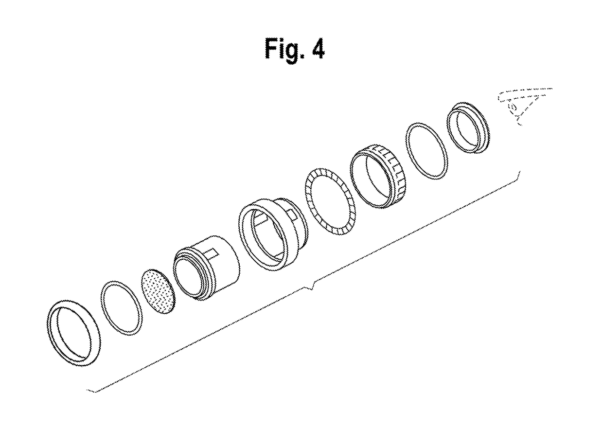
[0025]FIG. 4 diagrams the internal integration of the filter in a typical eyepiece of the NVS-14. The user's eye 17 is positioned at the end of the eyepiece assembly. The eyepiece assembly is attached to the NVD body by means of the threaded locking ring 14. Element 8 is a threaded retaining ring which is mounted on the optical cell collar 12. Element 9 is a retaining ring. Knurled ring 10 is rotated by the operator to achieve focus with fiduciary ring 11 providing indication to the operator of the adjustment. The optical cell collar 12 utilizes the grooves on the side of the optical cell 15 to effect longitudinal movement of ...


PUM


Abstract

This patent application discloses the use of specialized optical filters or similarly functional devices to improve the utility of Night Vision Devices (NVD) by placing these specialized filters in the internal optics train of the eyepiece such that the undesirable illumination of the user's face is reduced while at the same time maintaining the peripheral vision of the user and concomitantly reducing the dark adaptation time of the user when transitioning from the NVD to the unaided eye.

Description

CROSS-REFERENCE TO RELATED APPLICATIONS[0001]Not applicable.STATEMENT REGARDING FEDERALLY SPONSORED RESEARCH OR DEVELOPMENT[0002]Not applicable.NAMES OF PARTIES TO A JOINT RESEARCH AGREEMENT[0003]Not applicable.BACKGROUND[0004]This invention relates generally to Night Vision Devices, and more specifically to the placement of an optical filter or similarly functional device in relation to the Night Vision Device and to the device user's eye.[0005]Night Vision Devices (NVDs) refer to a group of electronic devices used to augment the vision of the user in low light and / or dark conditions. There are at least four classes of such devices distinguished by the type of illumination amplified by their respective electronics: image intensifiers, near infrared imaging, thermal imaging and combinations of these called fusion devices. Other types of devices may include infrared sources to illuminate the scene.[0006]These NVDs utilize a display to convert the electronic signals from the detectors...

Claims


Application Information

Patent Timeline
Patent Type & Authority Applications(United States)
IPC IPC(8): G02B23/12G02B5/20G02B25/00
CPCG02B23/12G02B25/001G02B5/208G02B23/125
Inventor KREUTZIG, KIRK
Owner SPECTRUM TECH INT LTD
Learn More