
Systems and Methods for Acoustic Radiation Control

a technology of acoustic radiation and control system, applied in the direction of active noise control, instruments, transportation and packaging, etc., can solve the problems of acoustic radiation with significant directionality, long propagation distance, health risk,

Active Publication Date: 2018-11-08
AURORA FLIGHT SCI CORP
View PDF12 Cites 24 Cited by
  • Summary
  • Abstract
  • Description
  • Claims
  • Application Information

AI Technical Summary

Benefits of technology

The patent is about a method for reducing the noise and annoyance of electric motors. The method involves adjusting each motor to spread the acoustic energy across a range of frequencies and improve the overall acoustic character of the motors to make them less detectable and not as annoying. This can be beneficial in certain situations where reducing noise is important, such as in electric vehicles or home appliances.

Problems solved by technology

Indeed, noise pollution, and the desire to control (or reduce) it, has resulted in significant regulation preventing or otherwise inhibiting, operation of aircraft in close proximity to people and / or residential areas.
Furthermore, this acoustic radiation has significant directionality and can propagate long distances.
Beyond nuisance, high-intensity noise produced in certain applications can pose a health risk and can even pose a risk to nearby materials' structural integrity.
Rotor-driven aircraft are particularly prone to generate acoustic radiation, where the aircraft's rotors / propellers are a dominant source of acoustic radiation.
Accordingly, acoustic radiation emitted by propellers / fans / rotors is an undesirable byproduct of their primary function—to generate thrust / propulsion.

Method used


Image

  • Systems and Methods for Acoustic Radiation Control
  • Systems and Methods for Acoustic Radiation Control
  • Systems and Methods for Acoustic Radiation Control

Examples


Embodiment Construction

[0034]Preferred embodiments of the present invention will be described hereinbelow with reference to the accompanying drawings. The components in the drawings are not necessarily drawn to scale, the emphasis instead being placed upon clearly illustrating the principles of the present embodiments. For instance, the size of an element may be exaggerated for clarity and convenience of description. Moreover, wherever possible, the same reference numbers are used throughout the drawings to refer to the same or like elements of an embodiment. In the following description, well-known functions or constructions are not described in detail because they may obscure the invention in unnecessary detail. No language in the specification should be construed as indicating any unclaimed element as essential to the practice of the embodiments. In the following description, it is understood that terms such as “first,”“second,”“top,”“bottom,”“side,”“front,”“back,” and the like, are words of convenienc...


PUM


Abstract

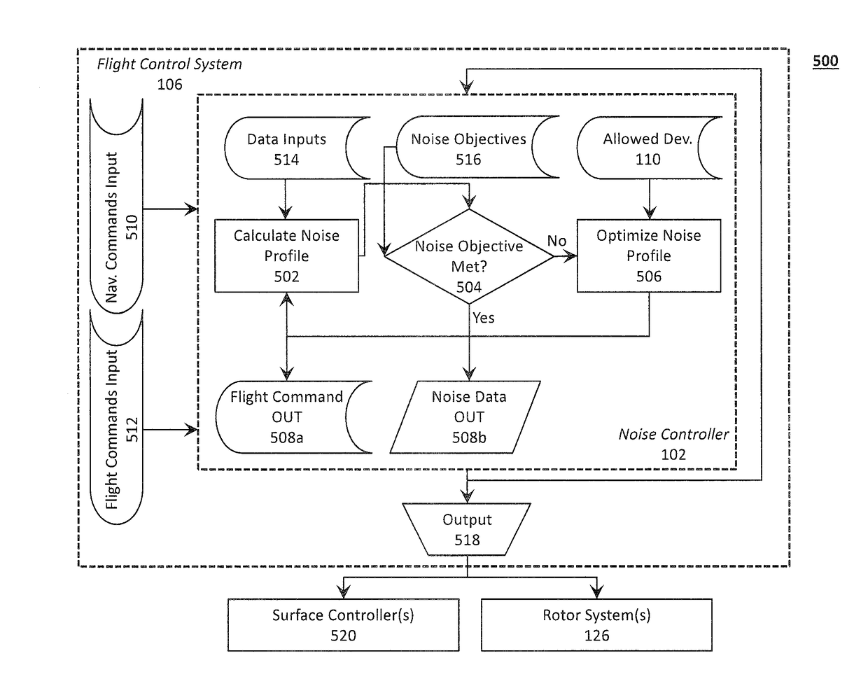
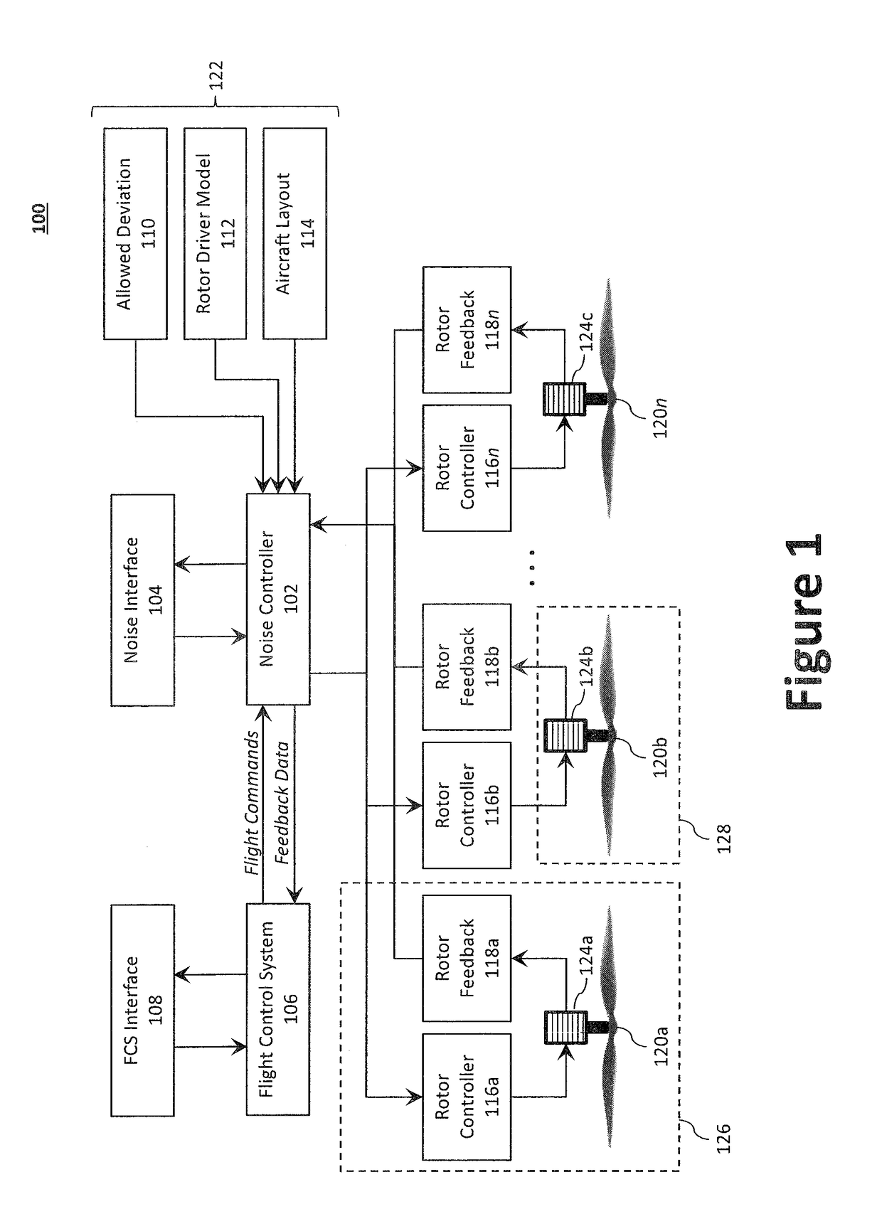
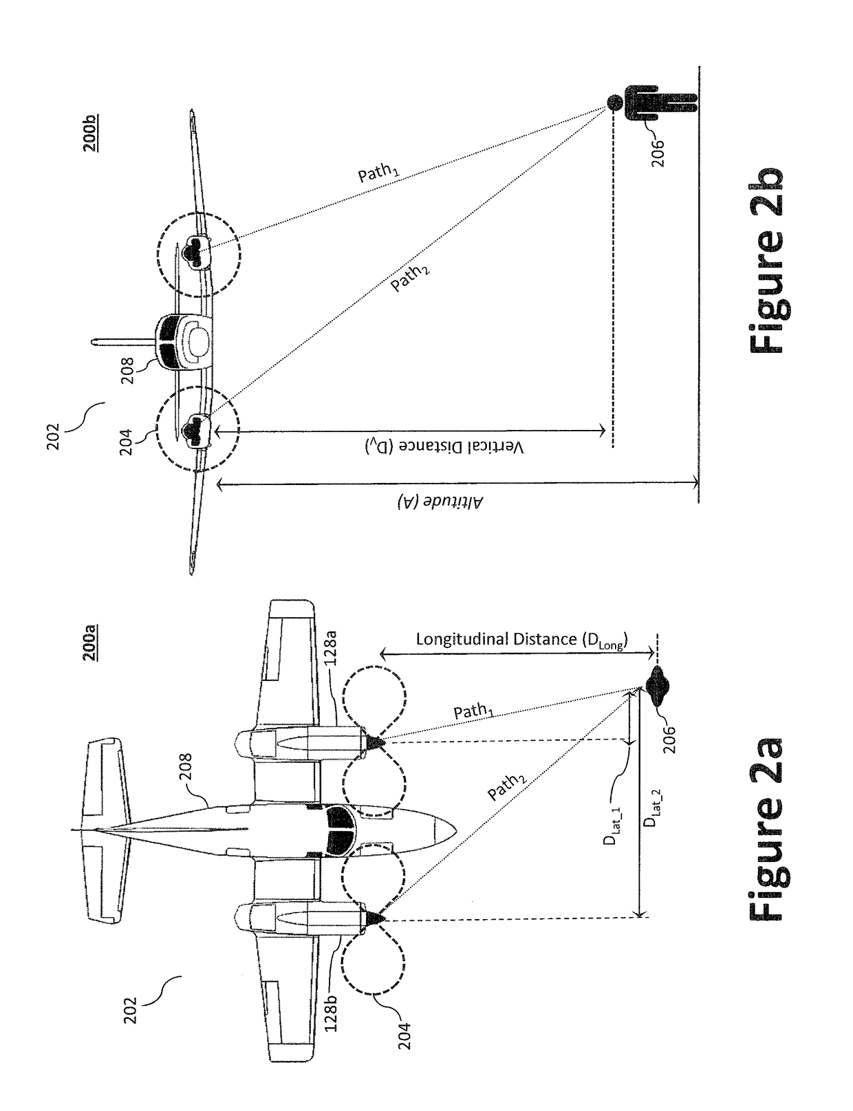
Disclosed is a system for controlling acoustic radiation from an aircraft. The system comprising a plurality of rotor systems (one or more) and a noise controller configured to regulate acoustic radiation from the plurality of rotor systems. The noise controller can be configured to regulate a commanded flight setting from the flight control system and to output a regulated flight setting to the plurality of rotor systems. Based on the regulated flight setting, the plurality of rotor systems are configured to generate, individually and in aggregate, acoustic radiation having a target acoustic behavior. The target acoustic behavior may be achieved using beamforming techniques to, for example, change the directionality of acoustic radiation from the plurality of rotor systems, or otherwise tune the acoustic radiation to reduce detectability and / or annoyance.

Description

TECHNICAL FIELD[0001]The present invention relates to a system and method for controlling acoustic radiation, more specifically to a system and method for controlling the acoustic radiation generated and / or emitted by an aircraft's propellers, fans, and / or rotors.BACKGROUND[0002]Managing the aural characteristics (the combination of the all of the acoustically radiating sources) of an aircraft is important in many environments. Minimizing annoyance to passengers and people on the ground (known as noise pollution) is important to civil applications, while avoiding detection is important to military aircraft utility. Indeed, noise pollution, and the desire to control (or reduce) it, has resulted in significant regulation preventing or otherwise inhibiting, operation of aircraft in close proximity to people and / or residential areas. Furthermore, this acoustic radiation has significant directionality and can propagate long distances. Beyond nuisance, high-intensity noise produced in cer...

Claims


Application Information

Patent Timeline
IPC IPC(8): B64C27/57B64C11/30B64C39/02G10K11/175
CPCB64C27/57B64C11/305B64C39/024G10K11/175G10K2210/1281B64C2201/024B64C11/46G10K2200/10B64C2220/00G10K11/161B64C39/02B64U20/20B64C2027/7205G10K11/17813G10K11/1781B64U2201/20
Inventor KEARNEY-FISCHER, MARTIN
Owner AURORA FLIGHT SCI CORP
Learn More