Binding component holding sheet, binding component separation mechanism and bookbinding apparatus
a technology of binding components and separation mechanisms, which is applied in the field of binding component separation mechanisms and bookbinding apparatuses, can solve the problems of difficult to take out the coil, inability to securely apply a force to separate the inability to secure the separation of the coil from the sheet, so as to reduce the number of punch chad generation
- Summary
- Abstract
- Description
- Claims
- Application Information
AI Technical Summary
Benefits of technology
Problems solved by technology
Method used
Image

Examples
first embodiment
Configuration Example of Coil Holding Sheet of First Embodiment
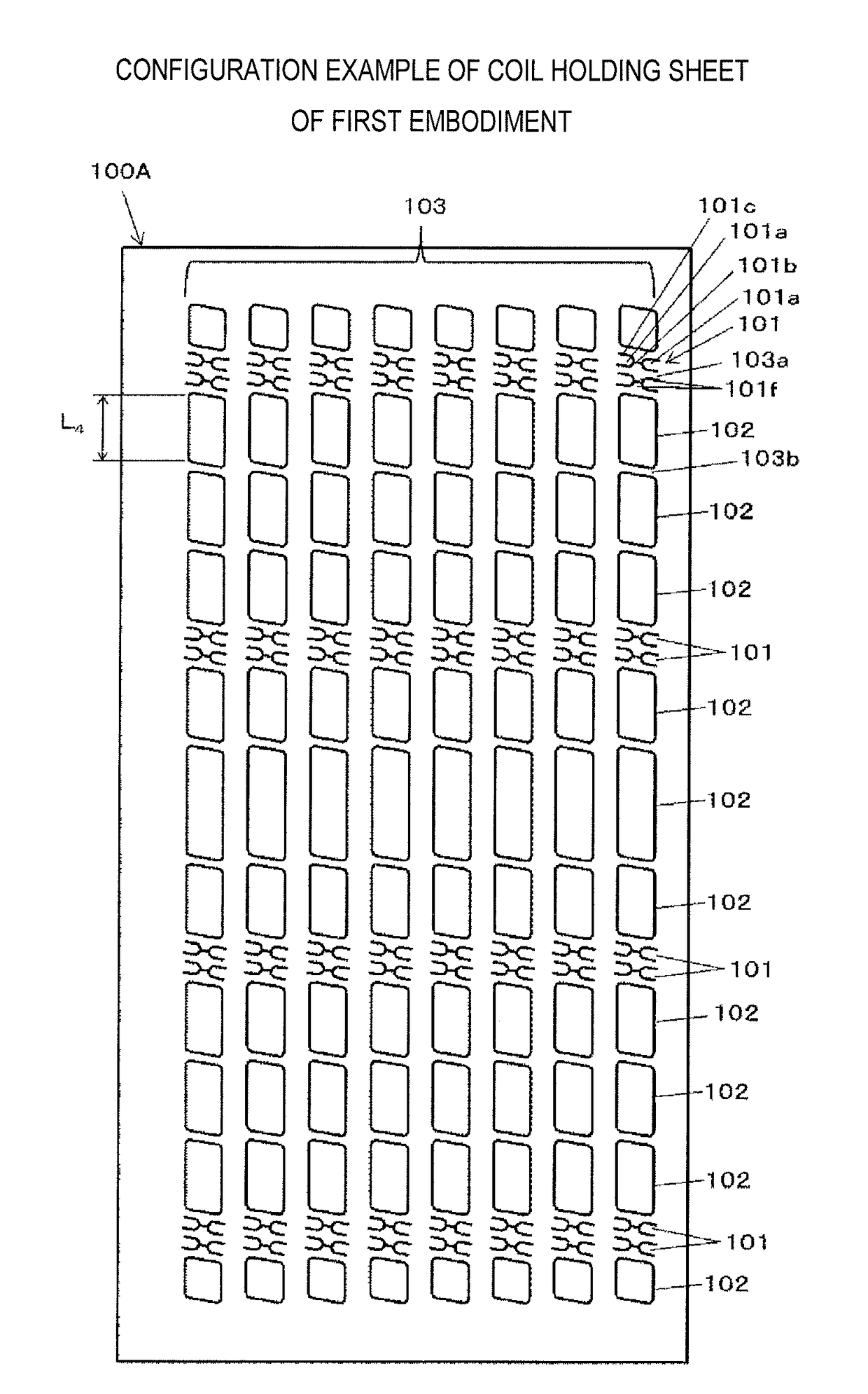
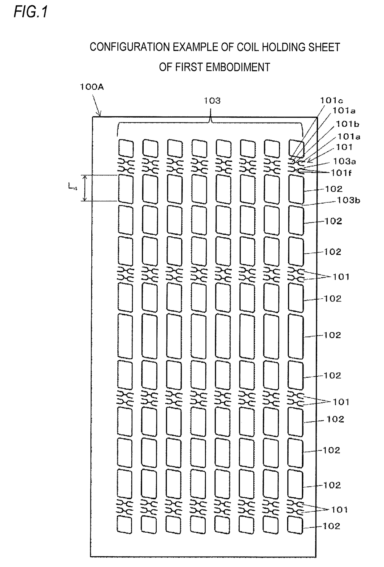
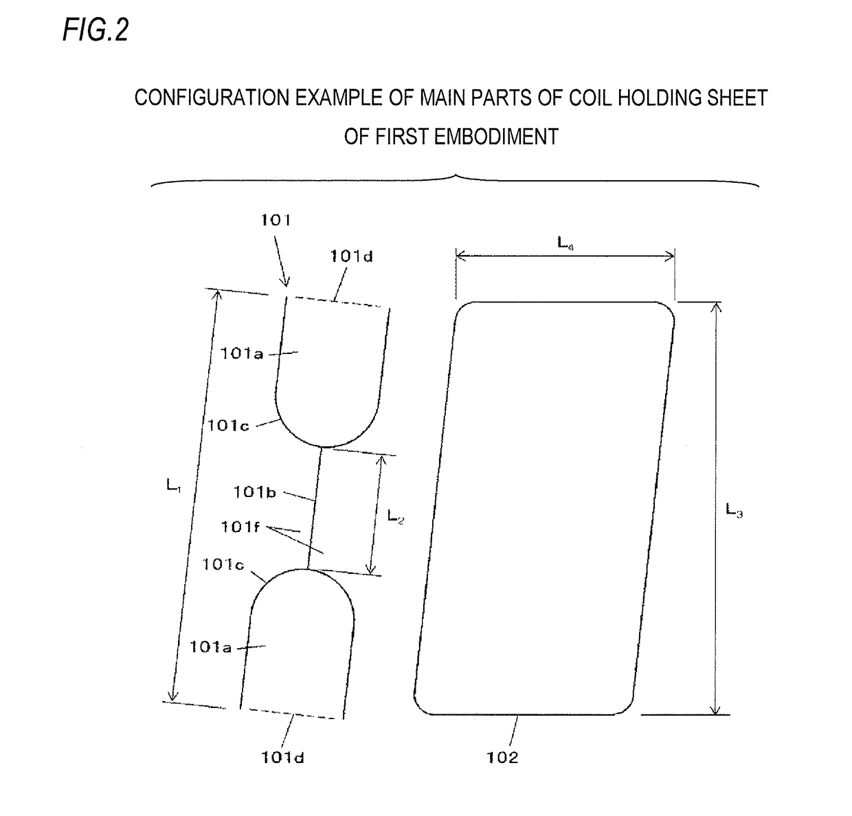
[0190]FIG. 1 is a front view depicting an example of a coil holding sheet of a first embodiment, and FIG. 2 is a front view depicting a configuration of main parts of the coil holding sheet of the first embodiment. FIGS. 3 to 7 depict the coil holding sheet of the first embodiment, to which coils are held. FIG. 3 is a front view of the coil holding sheet of the first embodiment, to which coils are held. FIG. 4 is a rear view of the coil holding sheet of the first embodiment, to which coils are held. FIG. 5 is a side view of the coil holding sheet of the first embodiment, to which coils are held. FIG. 6 is a plan view of the coil holding sheet of the first embodiment, to which coils are held. FIG. 7 is a perspective view of the coil holding sheet of the first embodiment, to which coils are held.
[0191]Also, FIGS. 8 and 9 are side views depicting a configuration of main parts of the coil holding sheet of the first embodimen...
second embodiment
Configuration Example of Coil Holding Sheet of Second Embodiment
[0289]FIG. 35 is a front view depicting an example of the coil holding sheet of a second embodiment. FIG. 36 is a front view depicting a configuration of main parts of the coil holding sheet of the second embodiment. FIGS. 37 to 41 depict the coil holding sheet of the second embodiment, to which coils are held. FIG. 37 is a front view of the coil holding sheet of the second embodiment, to which coils are held. FIG. 38 is a rear view of the coil holding sheet of the second embodiment, to which coils are held. FIG. 39 is a side view of the coil holding sheet of the second embodiment, to which coils are held. FIG. 40 is a plan view of the coil holding sheet of the second embodiment, to which coils are held. FIG. 41 is a perspective view of the coil holding sheet of the second embodiment, to which coils are held.
[0290]A coil holding sheet 100B of the second embodiment has holders 104 configured to hold the coil 200, and the...
third embodiment
Configuration Example of Coil Holding Sheet of Third Embodiment
[0366]FIG. 60 is a front view depicting an example of the coil holding sheet of a third embodiment. FIG. 61 is a front view depicting a configuration of main parts of the coil holding sheet of the third embodiment. FIGS. 62 to 66 depict the coil holding sheet of the third embodiment, to which coils are held. FIG. 62 is a front view of the coil holding sheet of the third embodiment, to which coils are held. FIG. 63 is a rear view of the coil holding sheet of the third embodiment, to which coils are held. FIG. 64 is a side view of the coil holding sheet of the third embodiment, to which coils are held. FIG. 65 is a plan view of the coil holding sheet of the third embodiment, to which coils are held. FIG. 66 is a perspective view of the coil holding sheet of the third embodiment, to which coils are held.
[0367]A coil holding sheet 100C of the third embodiment has holders 105 configured to hold the coil 200, and the escape ho...
PUM
 Abstract
Description
Claims
Application Information
 - R&D
- Intellectual Property
- Life Sciences
- Materials
- Tech Scout
- Unparalleled Data Quality
- Higher Quality Content
- 60% Fewer Hallucinations
Browse by: Latest US Patents, China's latest patents, Technical Efficacy Thesaurus, Application Domain, Technology Topic, Popular Technical Reports.
© 2025 PatSnap. All rights reserved.Legal|Privacy policy|Modern Slavery Act Transparency Statement|Sitemap|About US| Contact US: help@patsnap.com