


Quick Research
Generate reliable direction feasibility study reports for your R&D in just a few steps.

Technical Q&A
Discover and master advanced knowledge NOW. Basics, ideas, possibilities, all at once.

Find Solutions
As an expert in R&D theories, this can generate solutions to your technical problems instantly.

Evaluate Feasibility
Analyze your overall solution with one click, know your potential R&D risks in advance.

Monitor Landscape
Get weekly tech updates, stay abreast of the latest tech innovations and key insights.
Vehicle rear portion structure
- Summary
- Abstract
- Description
- Claims
- Application Information
AI Technical Summary
Benefits of technology
Problems solved by technology
Method used
Image

Examples
first exemplary embodiment
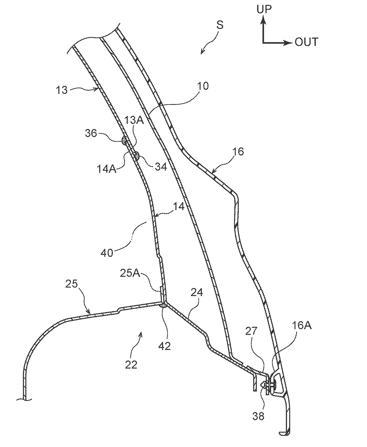
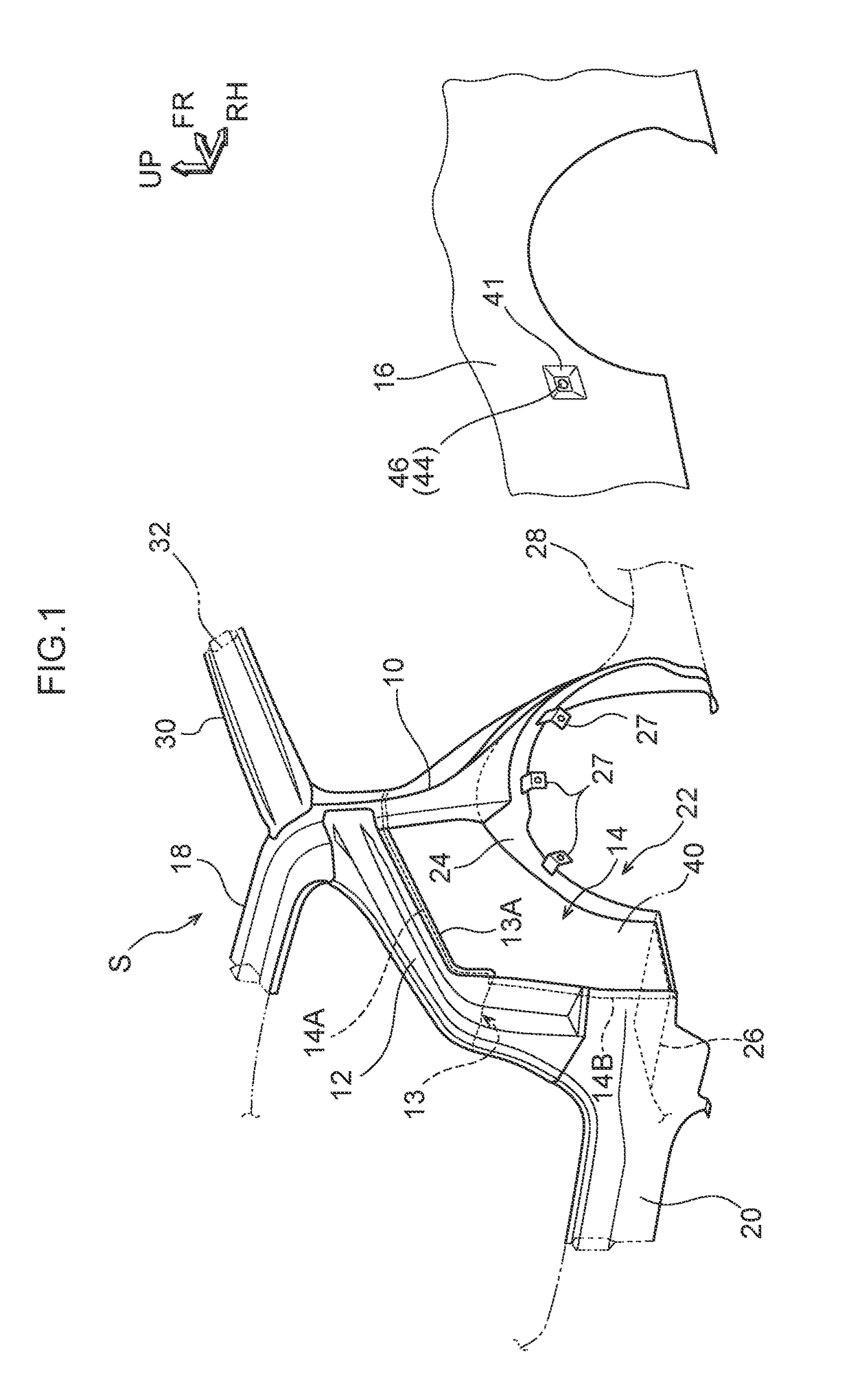
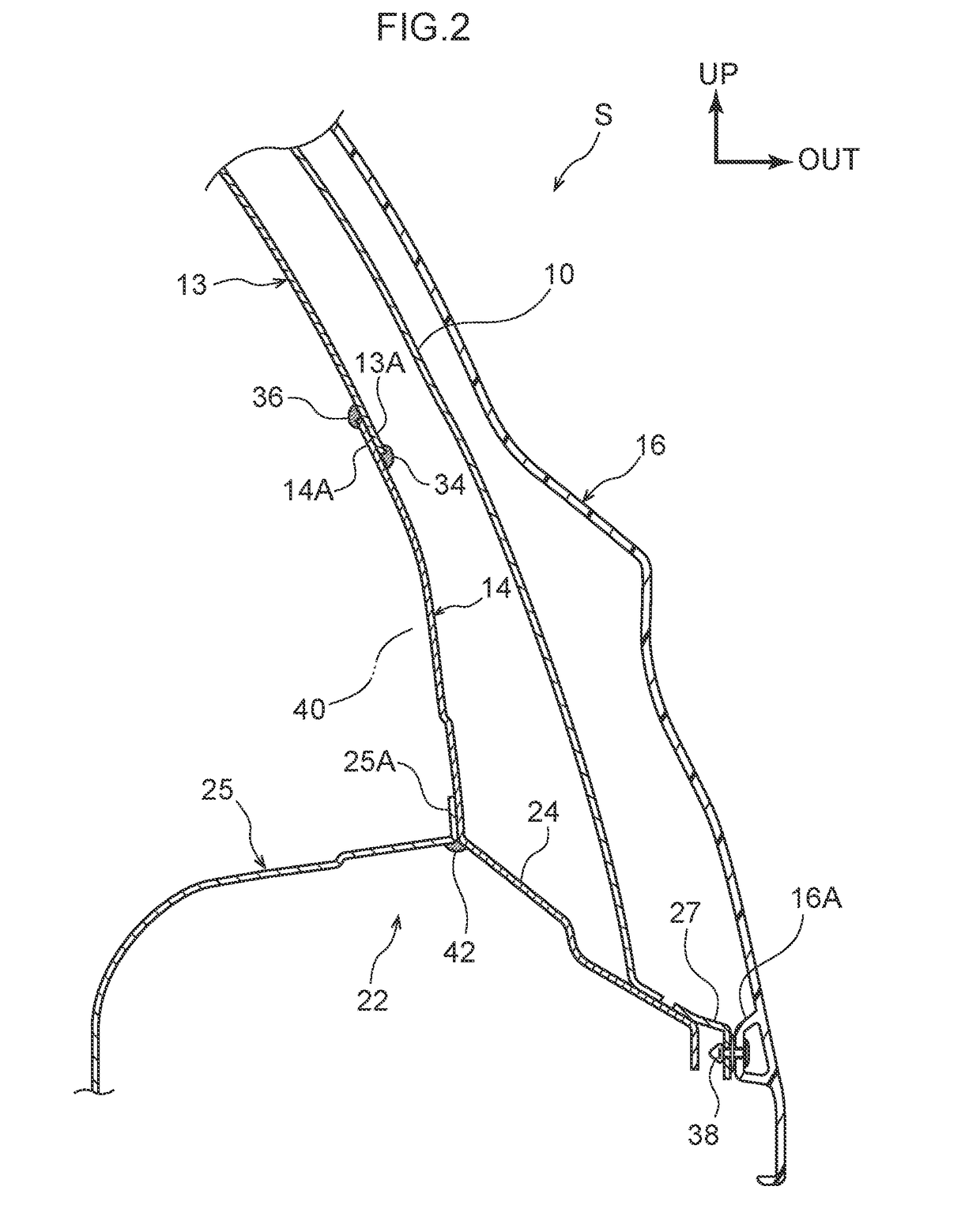
[0035]In FIG. 1 and FIG. 2, a vehicle rear portion structure S according to the present exemplary embodiment includes a rear pillar 10, a trough reinforcement 12, a roof side inner panel 13, a barrier wall 14, and a side panel 16. The trough reinforcement 12 and roof side inner panel 13 serve as examples of framework members.
[0036]The rear pillar 10 is, for example, a framework member that extends in the vehicle vertical direction at the vehicle rear portion. The upper end of the rear pillar 10 is joined to a rear header 18 that extends in the vehicle width direction. The rear pillar 10 is also joined to and an outer panel 24 of a rear wheel house 22. The lower end of the rear pillar 10 may be extended and joined to a rocker 28. The rocker 28 is a framework member that extends in the vehicle front-and-rear direction at a lower portion of a vehicle side portion.
[0037]The rear wheel house 22 is configured by the outer panel 24 and an inner panel 25 being joined together, and is provid...
second exemplary embodiment
[0051]FIG. 3 is a sectional diagram in a case in which a vehicle rear portion structure S according to the present exemplary embodiment is cut in the vehicle vertical direction in a vehicle rear side portion vicinity of the rear wheel house 22 in FIG. 1. In the vehicle rear portion structure S in FIG. 3, an inlet box portion 41 in a recess shape is provided in the side panel 16, and an inlet portion 44 is provided in the inlet box portion 41. The side panel 16 and the inlet box portion 41 are integrally formed of, for example, a resin. A penetrating hole 43 is formed in the inlet box portion 41. The inlet portion 44 may be inserted through the penetrating hole 43. The side panel 16 and the inlet box portion 41 may be integrally formed of a metal. A lid 52 is provided at the inlet box portion 41. The lid 52 covers the inlet box portion 41 in a case in which the inlet portion 44 is not being used.
[0052]The inlet portion 44 is, for example, a filler inlet 46, an electricity receiving p...
third exemplary embodiment
[0058]FIG. 4 is a sectional diagram in a case in which a vehicle rear portion structure S according to the present exemplary embodiment is cut in the vehicle vertical direction in a vehicle rear side portion vicinity of the rear wheel house 22 in FIG. 1. In the vehicle rear portion structure S in FIG. 4, the inlet box portion 41 is a separate body and is assembled to the side panel 16. The side panel 16 and the inlet box portion 41 are, for example, both constituted of resin. A flange 48 is formed integrally with the inlet box portion 41. An opening portion 49 that corresponds with the inlet box portion 41 is provided at an attachment region of the side panel 16 at which the inlet box portion 41 is attached. The flange 48 of the inlet box portion 41 is joined to a back face 16B (vehicle inner side face) of peripheral edges of the opening portion 49.
[0059]Because the side panel 16 and the inlet box portion 41 are separate bodies from one another before assembly, the side panel 16 and...
PUM
 Abstract
Description
Claims
Application Information
 - R&D Engineer
- R&D Manager
- IP Professional
- Industry Leading Data Capabilities
- Powerful AI technology
- Patent DNA Extraction
Browse by: Latest US Patents, China's latest patents, Technical Efficacy Thesaurus, Application Domain, Technology Topic, Popular Technical Reports.
© 2024 PatSnap. All rights reserved.Legal|Privacy policy|Modern Slavery Act Transparency Statement|Sitemap|About US| Contact US: help@patsnap.com