Inductor component
a technology of inductor components and components, applied in the direction of transformers/reacts mounting/support/suspension, inductances, inductances, etc., can solve the problems of interference between the inductor component and the adjacent device, for example, and achieve the effect of increasing the design flexibility of the terminal electrode of the inductor component and the land pattern on the circuit board
- Summary
- Abstract
- Description
- Claims
- Application Information
AI Technical Summary
Benefits of technology
Problems solved by technology
Method used
Image
Examples
first embodiment
[0049]A first embodiment will now be described.
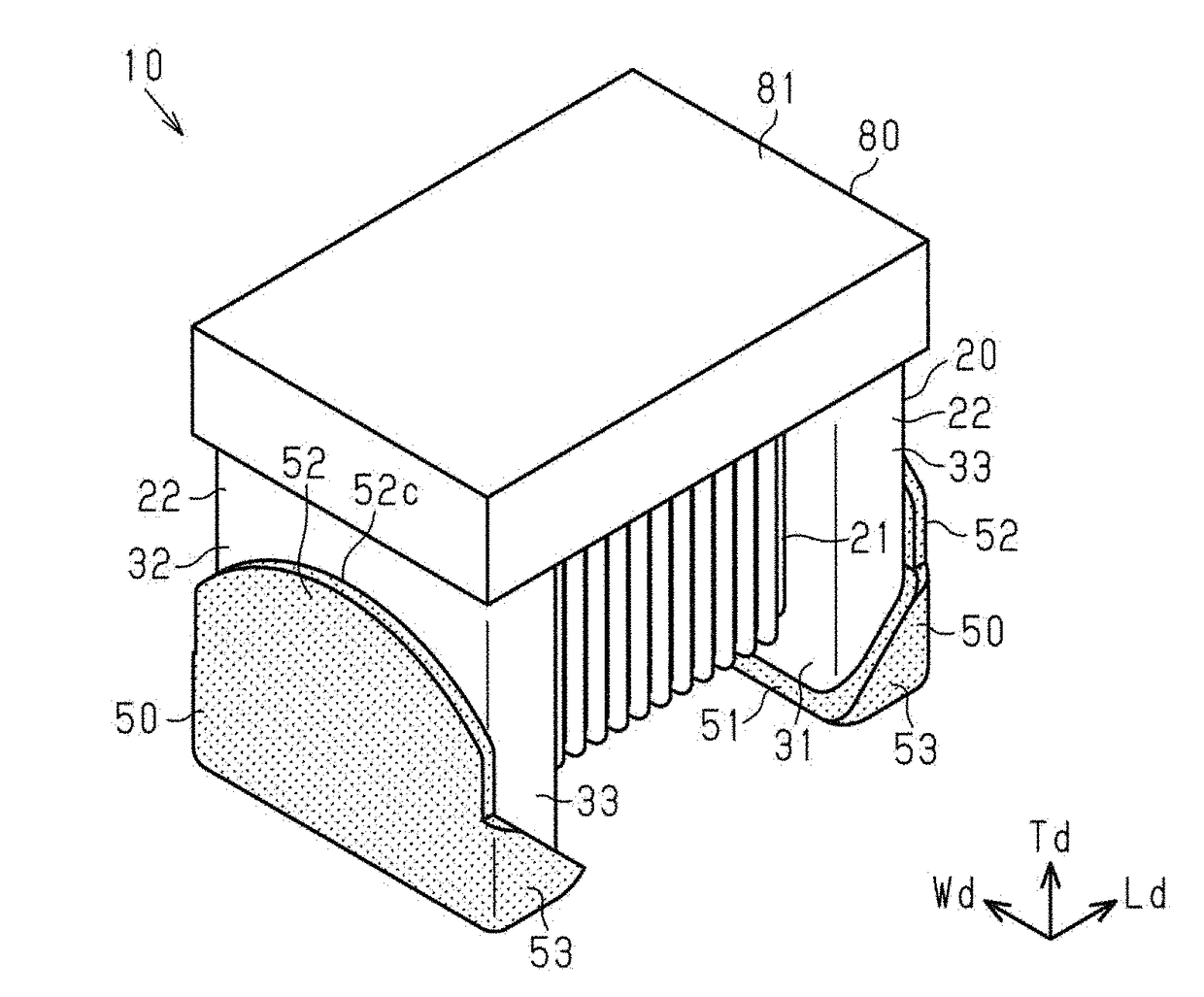
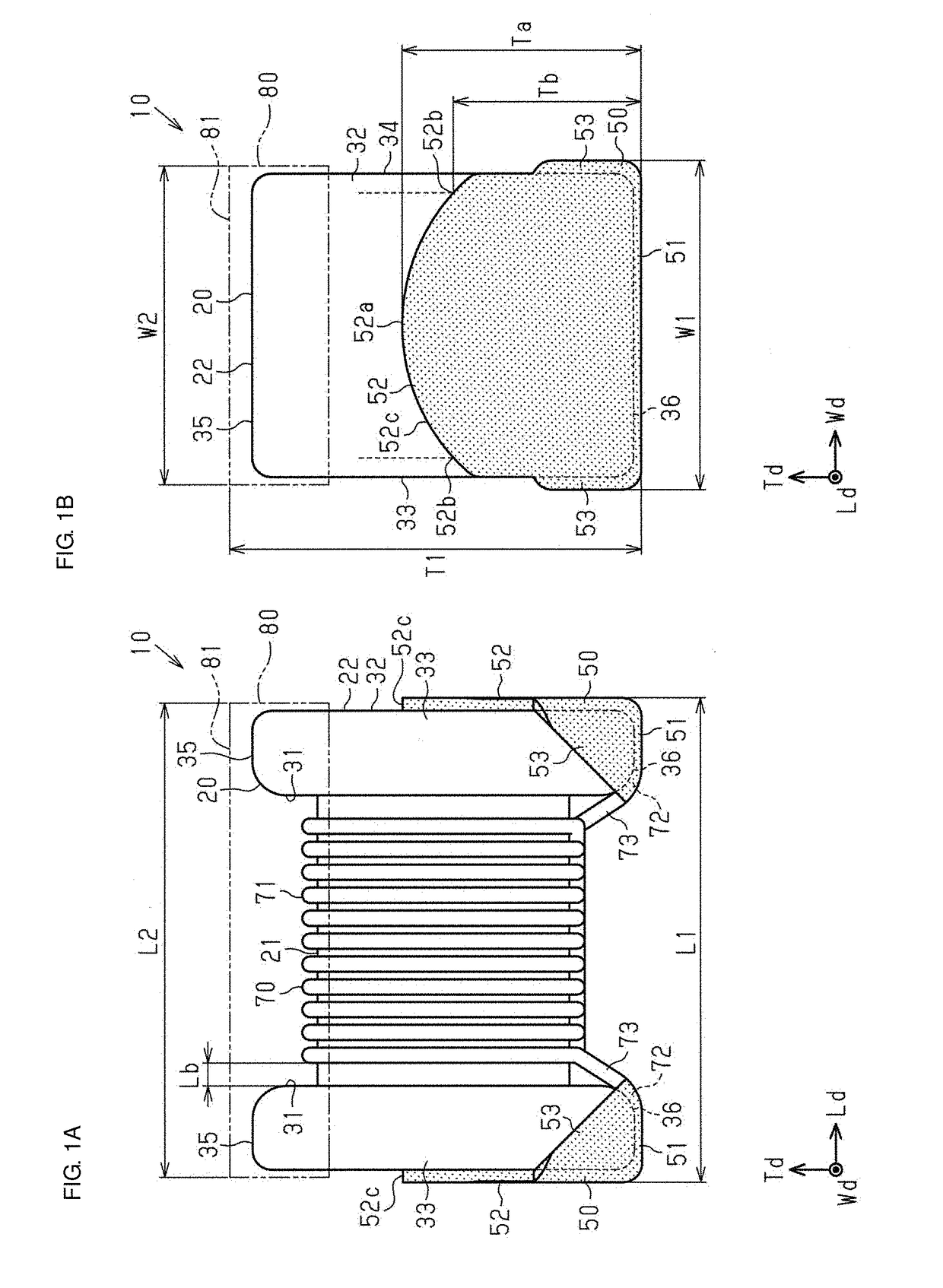
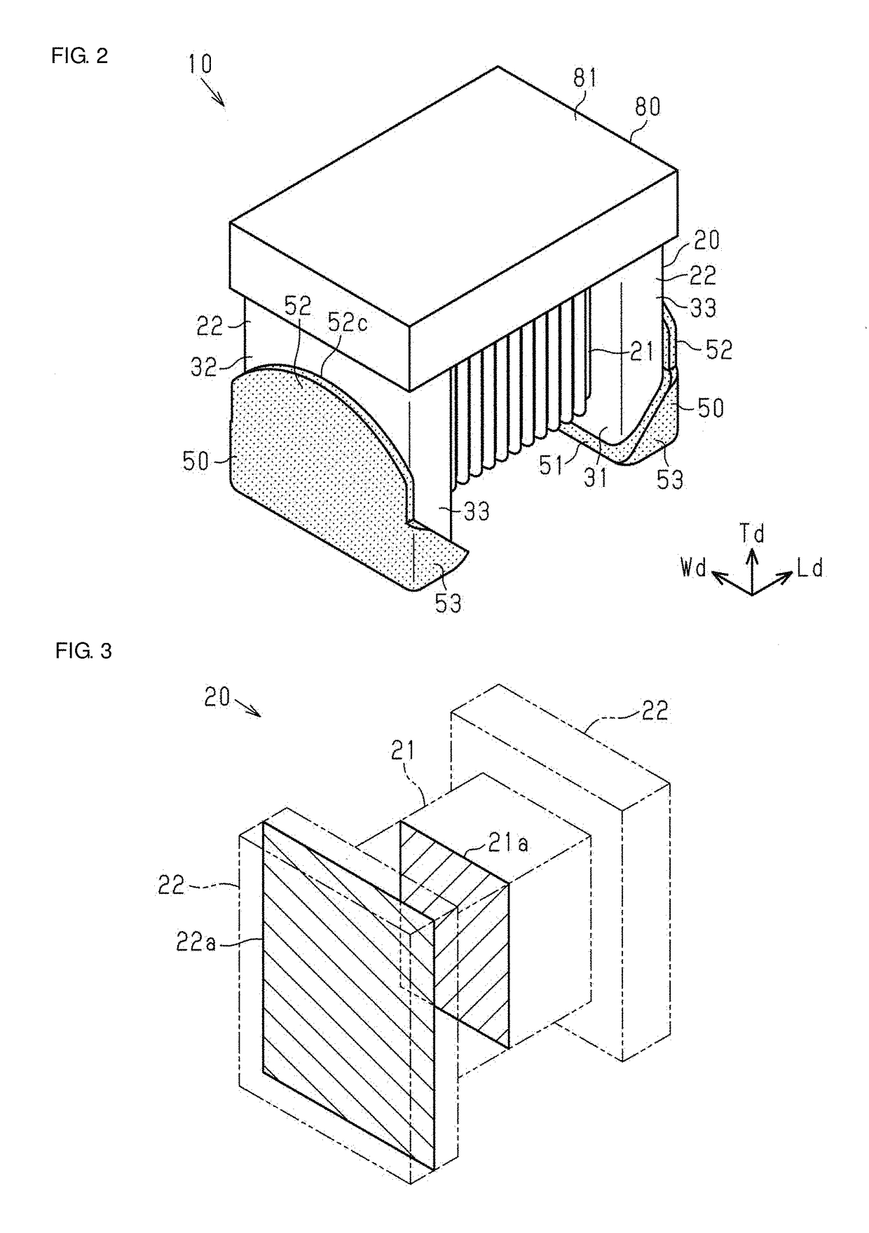
[0050]An inductor component 10 illustrated in FIGS. 1A, 1B, and FIG. 2 is, for example, a surface-mount inductor component to be mounted on, for example, a circuit board. The inductor component 10 may be used in various devices, such as smart phones and wrist-worn mobile electronic devices (for example, smart watches).
[0051]The inductor component 10 according to the present embodiment includes a core 20, a pair of terminal electrodes 50, and a wire 70. The core 20 includes a shaft 21 and a pair of supports 22. The shaft 21 is substantially rectangular parallelepiped shaped (rectangular prism shaped). The supports 22 extend perpendicularly to the longitudinal direction of the shaft 21 from both ends of the shaft 21. The shaft 21 is supported parallel to a circuit board by the supports 22. The supports 22 are formed integrally with the shaft 21 at both ends of the shaft 21.
[0052]The terminal electrodes 50 are formed on the respective supp...
second embodiment
[0124]A second embodiment will now be described.
[0125]In this embodiment, constituent members that are the same as those in the above-described embodiment are denoted by the same reference numerals, and description thereof may be partially or entirely omitted.
[0126]An inductor component 10a illustrated in FIGS. 8A, 8B, and 9 includes the core 20, the pair of terminal electrodes 50, and a wire 70a. The wire 70a is wound around the shaft 21 so as to form a single layer on the shaft 21. Both end portions of the wire 70a are connected to the respective terminal electrodes 50. The inductor component 10a is a wire-wound inductor component.
[0127]As illustrated in FIG. 8A, the wire 70a includes a wound portion 71 wound around the shaft 21, connected portions 72 connected to the terminal electrodes 50, and extending portions 73 that extend between the wound portion 71 and the connected portions 72. The connected portions 72 are connected to the bottom electrode sections 51 of the terminal el...
PUM
| Property | Measurement | Unit |
|---|---|---|
| length | aaaaa | aaaaa |
| height | aaaaa | aaaaa |
| thickness | aaaaa | aaaaa |
Abstract
Description
Claims
Application Information
 - R&D
- Intellectual Property
- Life Sciences
- Materials
- Tech Scout
- Unparalleled Data Quality
- Higher Quality Content
- 60% Fewer Hallucinations
Browse by: Latest US Patents, China's latest patents, Technical Efficacy Thesaurus, Application Domain, Technology Topic, Popular Technical Reports.
© 2025 PatSnap. All rights reserved.Legal|Privacy policy|Modern Slavery Act Transparency Statement|Sitemap|About US| Contact US: help@patsnap.com


