
Attaching Fixture and Display System

Inactive Publication Date: 2018-10-25
BROTHER KOGYO KK
View PDF0 Cites 2 Cited by
  • Summary
  • Abstract
  • Description
  • Claims
  • Application Information

AI Technical Summary

Benefits of technology

This patent is about a new system that allows for easy attachment and retraction of a member without obstructing the viewing field. The system has a simple design and is easy to use.

Problems solved by technology

Therefore, the structure becomes complex and, in some cases, cost increases.

Method used


Image

  • Attaching Fixture and Display System
  • Attaching Fixture and Display System
  • Attaching Fixture and Display System

Examples


Embodiment Construction

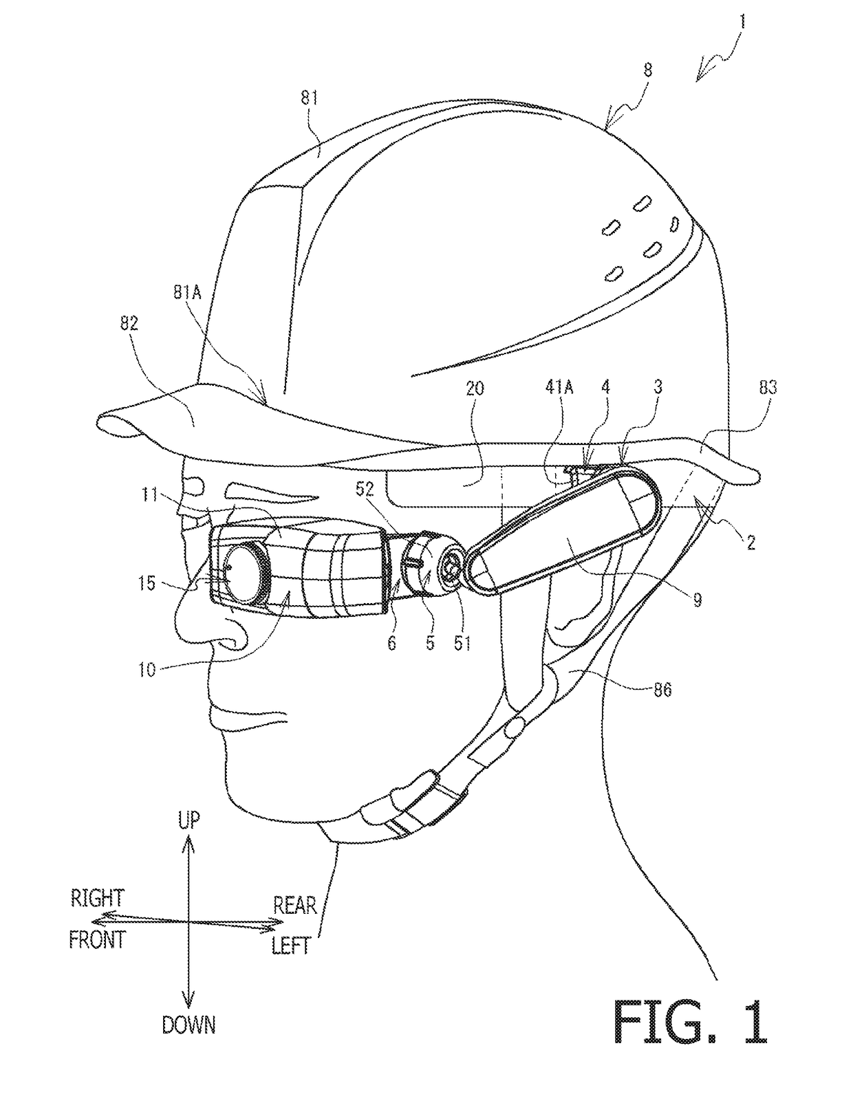
[0022]Hereinafter, referring to the drawings, an embodiment of the present disclosures will be described. As shown in FIG. 1, a head-mounted display (hereinafter, referred to as an “HMD”) 1 is a light transmission type see-through HMD. The HMD 1 includes a helmet 8, an attaching fixture 2, a connection fixture 9, and an image display device 10. Light from a scenery in front of an eye of a user is directly guided to the eye of the user by passing through a half mirror 14 (see FIG. 6) of the image display device 10. A projection type of the HMD 1 is a virtual image projection type. The half mirror 14 reflects light of an image displayed on a liquid crystal unit housed in the image display device 10 toward the left eye of the user. The HMD 1 is capable of making the user recognize the scenery in front of the eye of the user with the image superimposed.

[0023]Hereinafter, in order to assist in understanding the description of the drawings, an upper side, a lower side, a left side, a righ...


PUM


Abstract

An attaching fixture is provided with a main body part movable, with respect to a mounting fixture, between a first position and a second position. The main body part includes a supporting part configured to support an attached member, a first guiding part configured to guide a position of the supporting part, with respect to the mounting fixture, between the first position and the second position in a first direction, and a second guiding part configured to guide a position of the supporting part, with respect to the mounting fixture, between the second position and a third position in a second direction. The first direction and the second direction intersect with each other. A distance between the mounting fixture and the supporting part when the main body part is arranged at the third position is greater than the distance when the main body part is arranged at the second position.

Description

CROSS-REFERENCE TO RELATED APPLICATION[0001]This is a continuation application of International Application No. PCT / JP2017 / 001895 filed on Jan. 20, 2017, which claims priority from Japanese Patent Application No. 2016-014664 filed on Jan. 28, 2016. The entire disclosure of the prior application is incorporated herein by reference.BACKGROUNDTechnical Field[0002]The present disclosures relate to an attaching fixture for attaching an attached member on a head, a display system and an attaching system.Related Art[0003]An attaching fixture for attaching an attached member, such as an optical apparatus or a display device, on the head has been known. Further, an attaching fixture having a function of retracting the attached member to a position that does not obstruct a viewing field when the attached member is not in use has been proposed. An optical apparatus holding device for attaching an optical apparatus on a helmet is conventionally known. In the optical device holding apparatus, th...

Claims


Application Information

Patent Timeline
IPC IPC(8): G09F9/00H04N5/64G02B27/01
CPCG09F9/00H04N5/64G02B27/017G02B7/04G02B27/0179G02B2027/0181G02B27/0176
Inventor SUGIMOTO, KIYOSHITERADA, KOHEI
Owner BROTHER KOGYO KK
Learn More