System and Method of Identifying a Module in a Stack Light

a module and stack light technology, applied in the field of stack lights, can solve problems such as assembly errors

Active Publication Date: 2018-10-18
ROCKWELL AUTOMATION TECH
View PDF4 Cites 5 Cited by
  • Summary
  • Abstract
  • Description
  • Claims
  • Application Information

AI Technical Summary

Problems solved by technology

While modularity of the stack light construction is intended to provide a customer with the ability to rapidly fabricate a wide variety of different stack light configurations out of readily available (stocked) components, the large number of configurations, however, can lead to an error in assembly.

Method used


Image

  • System and Method of Identifying a Module in a Stack Light
  • System and Method of Identifying a Module in a Stack Light
  • System and Method of Identifying a Module in a Stack Light

Examples


first embodiment

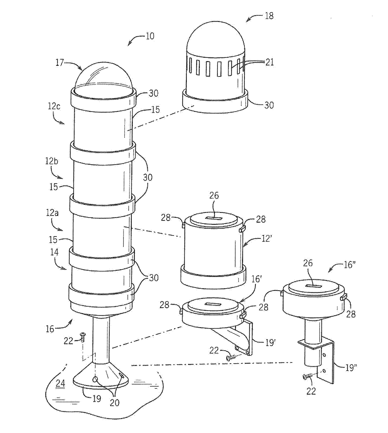
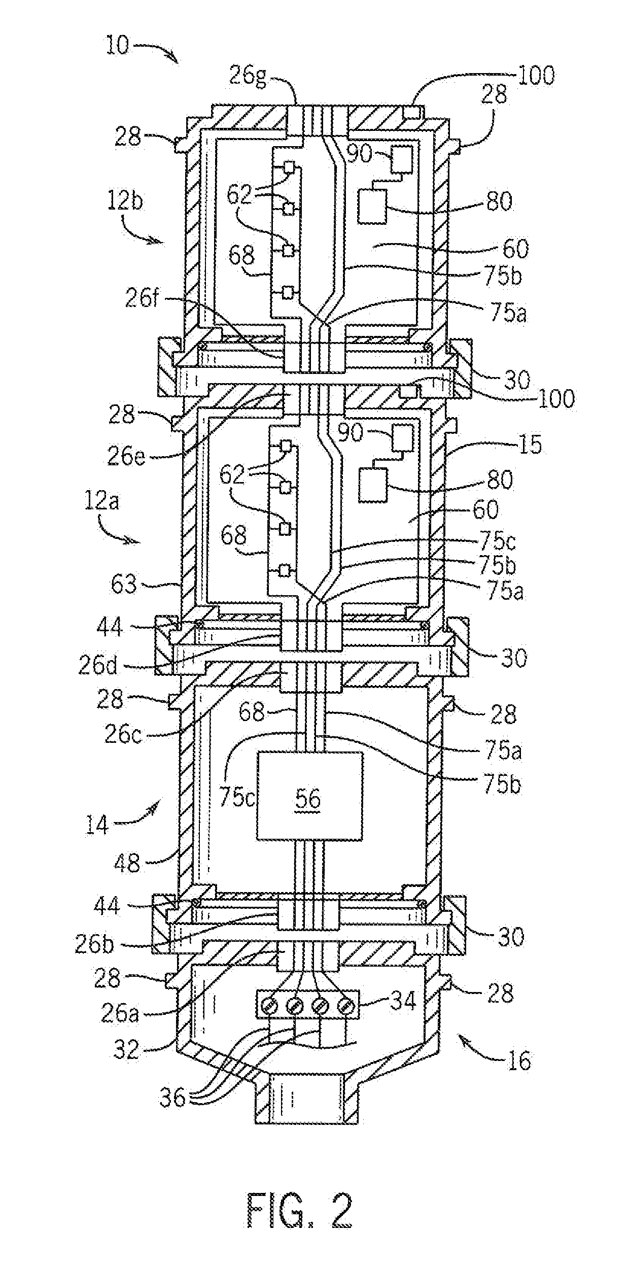
[0046]A illustrated in FIGS. 3 and 4, the electrical connectors 26 according to the module 12 are illustrated. The electrical connector 26 on the upper surface 104 includes multiple slots 27 and multiple terminals 63 along an upper edge 61 of the circuit board 60. The electrical connector 26 on the lower end of the module 12 includes multiple terminals 67 along the lower edge 65 of the circuit board 60. The upper surface 104 of the housing 15 includes multiple slots 27 of varying lengths extending therethrough. The slots 27 are configured to receive terminals 67 along the lower edge 65 of the circuit board 60 from another module 12 and to allow rotation of the terminals 67 within the slots 27. Because the terminals 67 proximate the outer periphery will travel a greater distance than the terminals 67 in the center of the module for the same amount of rotation of the module, the length of the slots 27 along the outer periphery of the upper surface 104 are longer than the length of the...

second embodiment

[0047]As illustrated in FIG. 7, the electrical connectors 26 according to the module 12 are illustrated. The electrical connector 26 on the upper surface 104 includes spring terminals 69 mounted to the upper surface 104 of the housing 15 and fixed terminals 63 along the upper edge 61 of the circuit board. The electrical connector 26 on the lower end of the module 12 includes multiple terminals 67 along the lower edge 65 of the circuit board 60. As two modules 12 are rotated together, the lower terminals 67 engage the spring terminals 69 causing downward deflection. When the two modules are rotated apart, the spring terminals 69 return to an upward, unbiased position. Either one or both ends of the spring terminals 69 are, in turn electrically connected to the fixed terminals 63 along the upper edge 61 of the circuit board. The biasing force between the spring terminals 69 of one module and the lower terminals 67 of the other module establishes a good electrical connection between th...


PUM

PropertyMeasurementUnit
diametersaaaaaaaaaa
diametersaaaaaaaaaa
diametersaaaaaaaaaa

Abstract

A system to verify the identity of modules within a stack light is disclosed. A sensor is mounted to a circuit board inserted within a housing of the module, and a target is mounted to or integrally formed in the housing. The sensor detects and generates a signal corresponding to the detected target. Different targets or locations for the target are provided for each housing. The module, a base for the stack light, or a remote controller in communication with the stack light identifies the housing in which the circuit board is mounted based on the feedback signal generated by detecting the target. At power-up, a routine may initiate a verification routine by which each module in the stack light determines the type of housing in which the circuit board for that module is located.

Description

BACKGROUND INFORMATION[0001]The present invention relates to stack lights, which convey visual and / or audible information regarding operating and / or fault conditions in an industrial environment, and in particular, to a stack light that includes a system for identifying the type of module present at each location within the stack configuration.[0002]Stack lights are typically constructed of modular components that may be flexibly interconnected to produce stacks having varying combinations, orders, numbers, and configurations of modules. The modules may have various configurations and may include, for example, beacon modules emitting different colors of light, audible modules emitting different tones or sounds, or power modules receiving input power at one voltage and supplying power to the different modules at one or more different voltage levels. Although each module may provide a different function, they typically utilize identical mechanical and electrical connectors such that o...

Claims


Application Information

Patent Timeline
Patent Type & Authority Applications(United States)
IPC IPC(8): G01N21/27H05K1/18H05K5/00H05K5/02G01J3/50G01N27/72G01R19/00
CPCG01N21/27H05K1/181H05K5/0021H05K5/0247H05K2201/10151G01N27/72G01R19/0084G01R19/0092G01J3/505H05K1/117H05K1/142H05K2201/1034
Inventor PREISCHEL, WILL J.CASPERS, JOHN P.DUFFY, PATRICK K.
Owner ROCKWELL AUTOMATION TECH
Why Eureka
Try Eureka