Aircraft propulsion assembly equipped with a main fan and with at least one offset fan

a technology of propulsion assembly and main fan, which is applied in the field of aerospace, can solve the problems of generating a loud noise, limiting the bypass ratio, and complex implementation of this type of transmission system, and achieve the effect of increasing the bypass ratio

Active Publication Date: 2018-10-04
SN DETUDE & DE CONSTR DE MOTEURS DAVIATION S N E C M A
View PDF0 Cites 2 Cited by
  • Summary
  • Abstract
  • Description
  • Claims
  • Application Information

AI Technical Summary

Benefits of technology

[0007]In particular, the object thereof is to provide an arrangement which makes it possible to maintain a known architecture while at the same time increasing the bypass ratio.DISCLOSURE OF THE INVENTION
[0013]This configuration therefore makes it possible to simplify the design of a propulsion assembly while maintaining a known architecture onto which at least one additional fan module is integrated. In particular, by having a turbine dedicated to each fan and independent fan flows, the aerodynamic efficiency of each turbine and each fan is optimised in an independent manner, which results in better overall efficiency for the propulsion assembly.
[0037]at least the turbomachine or the auxiliary fan which is mounted on the wing comprises thrust reversal means which are able to deflect the air flow which passes through it at least upwards and / or laterally.
[0038]at least the auxiliary fan or the turbomachine which is fixed under the wing comprises thrust reversal means which are able to deflect the air flow which passes through it at least laterally in part.
[0052]When the second power transmission system is arranged downstream of the drive turbine of the main fan, and when the main and auxiliary fan(s) are driven by different and independent turbines, they are discharged together. When this second power transmission system is arranged upstream of the gas generator, it facilitates its integration because it is an area where the thermal-related stresses (operating temperature, expansion of parts etc.) are much lower.

Problems solved by technology

In the case of conventional turbojets having a turbine connected directly to the fan, the bypass ratios are limited by the peripheral speed at the head of the fan blades.
However, implementing this type of transmission system is complex.
The jet of the gas generator directly “shears” the air at an ambient temperature and generates a loud noise which is typical of fighter aircraft with a low bypass ratio or single flow.
In addition to this, the gas generator is highly exposed to the ingestion of foreign bodies, which is not the case for a conventional architecture where it is protected by a fan.

Method used


Image

  • Aircraft propulsion assembly equipped with a main fan and with at least one offset fan
  • Aircraft propulsion assembly equipped with a main fan and with at least one offset fan
  • Aircraft propulsion assembly equipped with a main fan and with at least one offset fan

Examples


Embodiment Construction

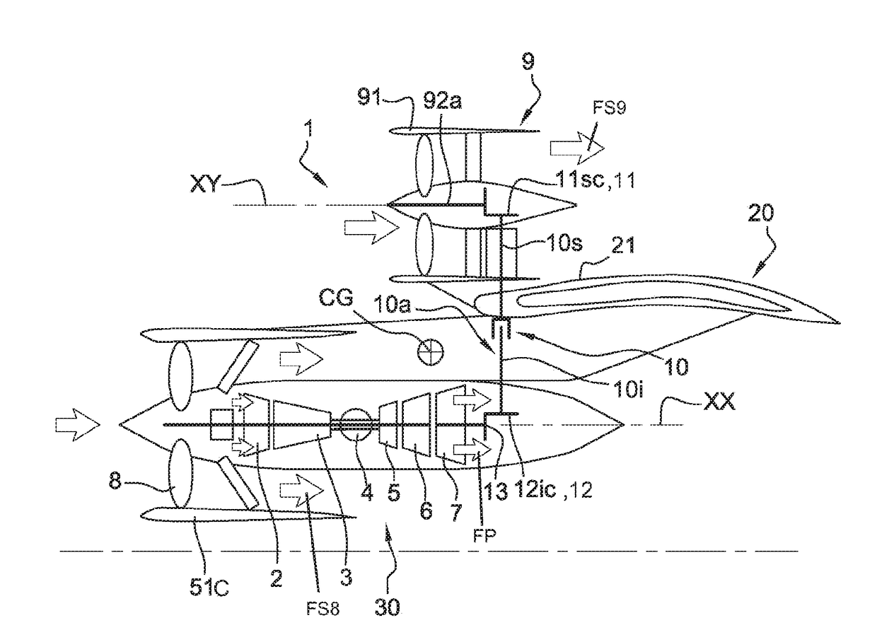
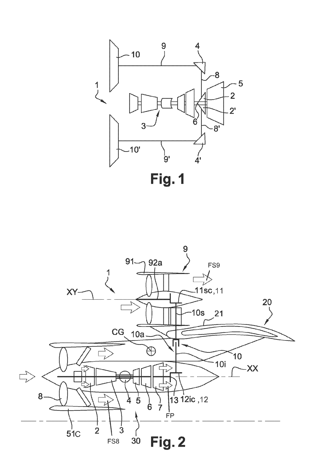
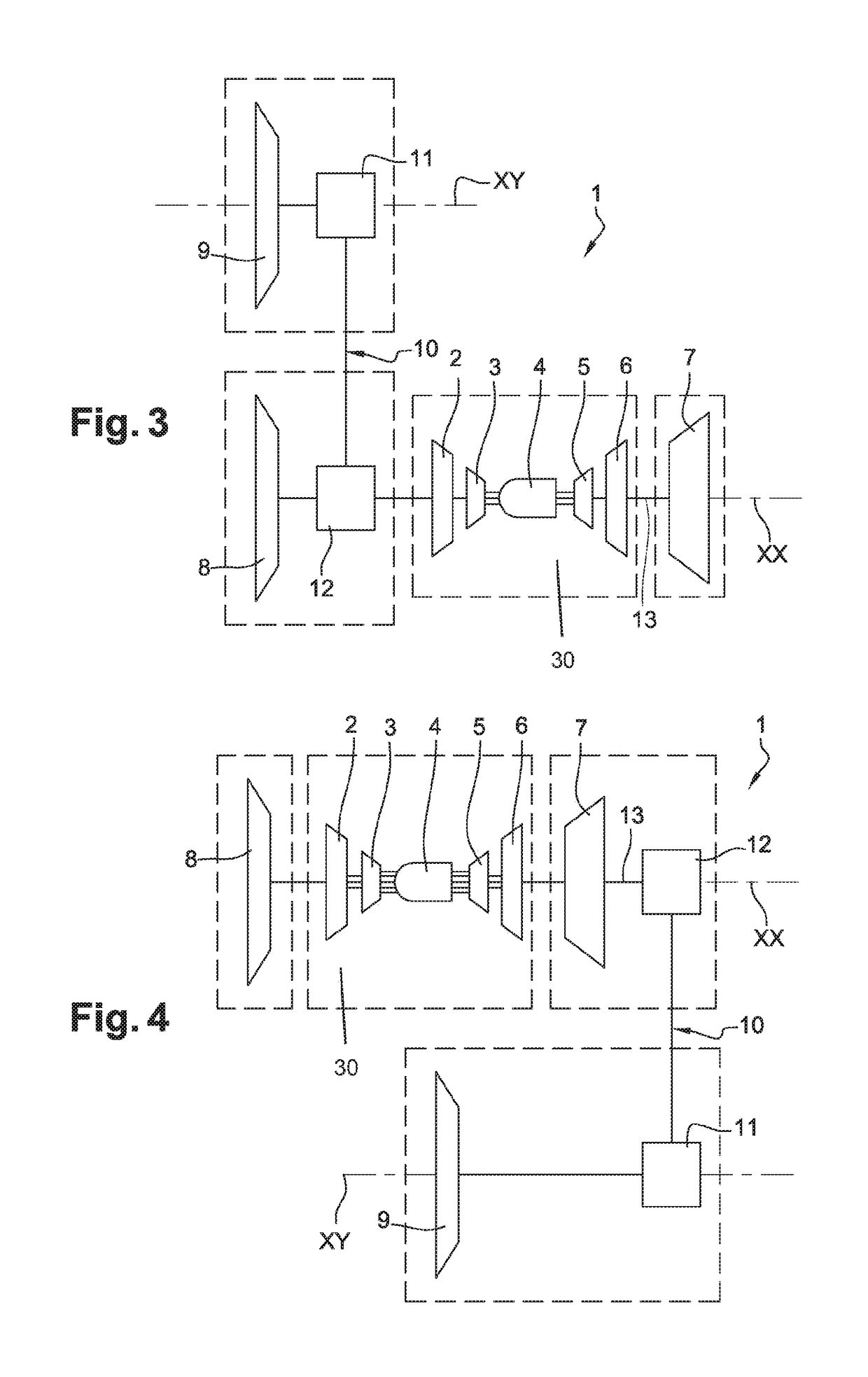
[0069]FIG. 2 shows a propulsion assembly 1 of an aircraft according to a first embodiment. In this example, the propulsion assembly 1 is shown mounted on the aerofoil 20 or wing of an aircraft. The aircraft comprises at least two of such propulsion assemblies, one on each wing 20. This propulsion assembly 1 comprises in this case a turbojet 40 comprising a gas generator 30 with a longitudinal axis XX. The invention can of course be applied to other types of turbomachines. The gas generator 30, following the longitudinal axis XX from upstream to downstream, a low-pressure (LP) compressor 2, a high-pressure (HP) compressor 3, a combustion chamber 4, a high-pressure (HP) turbine 5 and a low-pressure (LP) turbine 6. In the present invention, and generally speaking, the terms “upstream” and “downstream” are defined with respect to the flow of gas in the propulsion assembly or with respect to the direction of movement of the aircraft during flight. The LP compressor and the LP turbine are...


PUM


Abstract

An aircraft propulsion assembly comprising at least a main turbine mounted along a longitudinal axis, at least one main fan arranged upstream of the main turbine along the longitudinal axis and driven in rotation by the said main turbine, the said main fan being ducted by a main fan casing, an auxiliary turbine mounted along the longitudinal axis, the auxiliary turbine being independent of the main turbine, an auxiliary fan of axis offset with respect to the longitudinal axis and driven by the auxiliary turbine, the auxiliary fan being ducted by an auxiliary fan casing, the main casing being separate and distinct from the auxiliary casing so as respectively to generate a main secondary flow and an auxiliary secondary flow which remain independent of one another until they are discharged into the atmosphere.

Description

FIELD OF THE INVENTION[0001]The present invention concerns the aeronautical field and relates to a propulsion assembly comprising at least two fans which are driven by the same gas generator. It aims, in particular, to provide one fan positioned along the gas generator and at least one fan which is offset with respect to the axis of the gas generator.PRIOR ART[0002]The present applicant has undertaken work on a propulsion assembly architecture having at least two distributed fans. The objectives of these are to optimise propulsive efficiency by means of a high bypass ratio, i.e. the ratio of the secondary flow passing through the fan(s) to the primary air flow passing through the central body with the combustion chamber and turbines, while at the same time maintaining an acceptable ground clearance and reduced-size fans having a speed which is different from that of the turbine. An example of a propulsion assembly having offset fans is known from documents EP 2 574 546 and GB 2 400 ...

Claims


Application Information

Patent Timeline
Patent Type & Authority Applications(United States)
IPC IPC(8): F02C3/10B64D35/04B64D27/18F02C7/36F02K3/06B64D27/12B64D27/26
CPCF02C3/10B64D35/04B64D27/18F02C7/36F02K3/06B64D27/12B64D27/26F05D2250/312F05D2220/323F05D2240/14F05D2260/40311B64D2027/266F02K3/062F01D15/12F02C3/107F05D2220/36F05D2240/40F05D2240/60
Inventor CURLIER, AUGUSTIN MARC MICHELPERTAT, ADRIEN PIERRE JEANREIGNER, PIERRE- ALAIN JEAN PHILIPPESOULAT, LAURENTLEMARCHAND, KEVIN MORGANEBOUDEBIZA, TEWFIKCHARIER, GILLES ALAINNOWAKOWSKI, NATHALIE
Owner SN DETUDE & DE CONSTR DE MOTEURS DAVIATION S N E C M A
Why Eureka
Try Eureka