
Positioning system

a technology of positioning system and positioning plate, which is applied in the field of positioning plate, can solve the problems of not being able to chew, lack of teeth, and serious effects on an individual

Inactive Publication Date: 2018-10-04
KAMIL TECH LTD
View PDF2 Cites 3 Cited by
  • Summary
  • Abstract
  • Description
  • Claims
  • Application Information

AI Technical Summary

Benefits of technology

The present invention is a removable denture system that includes a personalized support beam attached to an individual's jaw bone, a personalized denture that matches the dental parameters of the individual, and a denture locking arrangement to secure and unlock the denture to the support beam. The support beam and denture have positioning grooves and corresponding positioning projections that fit snugly together, reducing movement between them when assembled. The technical effects include improved dental fit and comfort for the individual, and secure attachment of the denture to the support beam.

Problems solved by technology

Partial or complete loss of an individual's natural teeth, either or both at the upper and lower jaw, due to age, accident, diseases or other reasons has some serious effects on an individual, both functionally and socially.
Lack of teeth poses several serious functional problems such as not being able to chew, speech difficulties, etc.
While a denture can be accurately fitted to the alveolar ridge of an individual, it is difficult to retain a denture in position.
That is, during normal chewing or talking, the denture has a tendency to ride up out of position on the alveolar ridge, causing speech difficulties, chewing difficulties, and general unsatisfactory use of a denture.

Method used


Image

  • Positioning system
  • Positioning system
  • Positioning system

Examples


Embodiment Construction

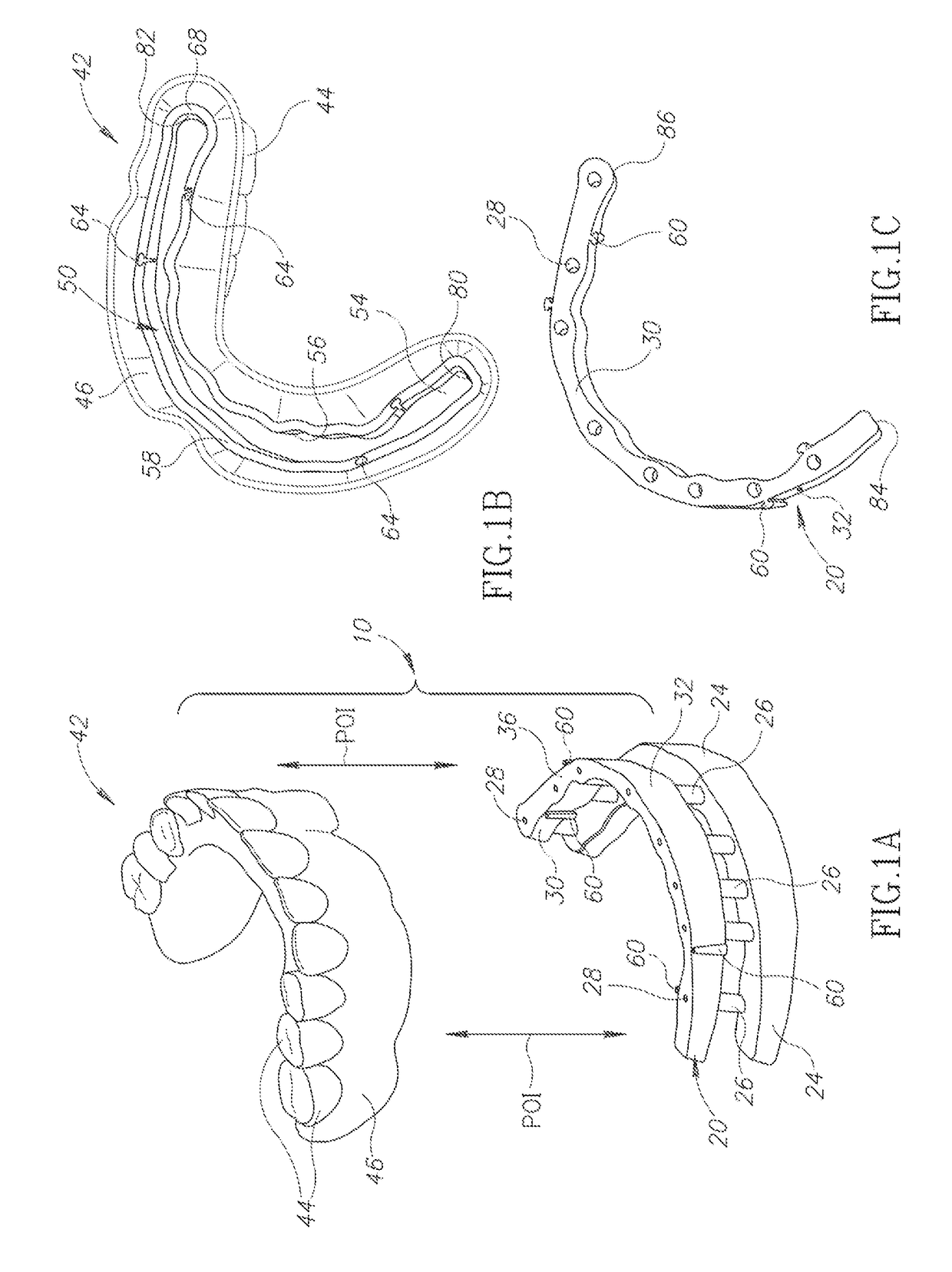
[0095]Attention is first directed to FIGS. 1 to 4 of the drawings illustrating a denture system generally designated 10, in accordance with the present disclosed subject matter. The denture system 10 comprises a support beam 20 fixedly secured to a jaw bone 24 (i.e., to the individual's alveolar ridge above the mucous membrane) of an individual, by a plurality of dental implants 26 received within the jaw bone 24 and wherein the support beam 20 is secured to the dental implants 26 by appropriate screws 28.

[0096]The support beam 20 follows the general arched shape of the jaw 24 and is configured with a lingual (inside) face 30, a labial (external) face 32 and a top surface 36.

[0097]The top surface 36 of the support beam 20 can be substantially flat and smooth over its entire length, as shown in the drawings. It should be appreciated, however, that the top surface can be at least partially rough and have small projections and / or recesses therealong.

[0098]The denture 42 is configured f...


PUM


Abstract

A positioning system is provided, comprising a support beam for attachment to an individual's jaw, and a removable denture comprising a bottom surface formed with a recess configured for receiving therein the support beam, the support beam and the recess being configured to preclude movement therebetween when the support beam is fully received within the recess. The support beam or the recess comprises one or more positioning grooves extending parallel to a path of insertion of the denture, and the other comprises one or more positioning protrusions laterally projecting therefrom and configured to be slidingly received within a corresponding positioning groove to provide at least a partially snug fit. The one or more positioning grooves and the corresponding one or more positioning protrusions are configured on one or more of a labial, lingual, or an face extending between the labial and lingual faces, of the recess and the support beam.

Description

[0001]This is a Continuation-In-Part of U.S. application Ser. No. 13 / 961,040 filed Aug. 7, 2013, which is a Continuation-In-Part of U.S. application Ser. No. 12 / 903,607 filed Oct. 13, 2010, the contents of which are hereby incorporated by reference in their entirety.FIELD OF THE INVENTION[0002]The present disclosed subject matter is generally in the field of positioning systems. More particularly, it is generally in the field of systems for positioning two elements, wherein one is received within the other.BACKGROUND OF THE INVENTION[0003]Partial or complete loss of an individual's natural teeth, either or both at the upper and lower jaw, due to age, accident, diseases or other reasons has some serious effects on an individual, both functionally and socially. Lack of teeth poses several serious functional problems such as not being able to chew, speech difficulties, etc. Even more so, a smile with a full set of white teeth is considered something to be desired, i.e., esthetics play ...

Claims


Application Information

Patent Timeline
Patent Type & Authority Applications(United States)
IPC IPC(8): A61C8/00A61C13/01A61C13/107
CPCA61C8/0048A61C13/01A61C13/0001A61C13/08A61C13/2255A61C13/235A61C13/225A61C8/0027
Inventor BERGER, UZI
Owner KAMIL TECH LTD
Learn More