Image capturing lens assembly, imaging apparatus and electronic device
a technology of image capturing and lens assembly, applied in the field of image capturing lens assembly and imaging apparatus, can solve the problems of hard to reduce the size of products and difficult to keep a balance among lens elements
- Summary
- Abstract
- Description
- Claims
- Application Information
AI Technical Summary
Benefits of technology
Problems solved by technology
Method used
Image

Examples
1st embodiment
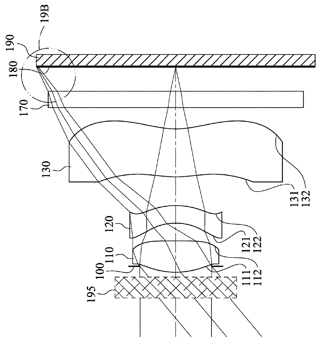
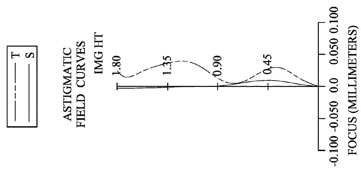
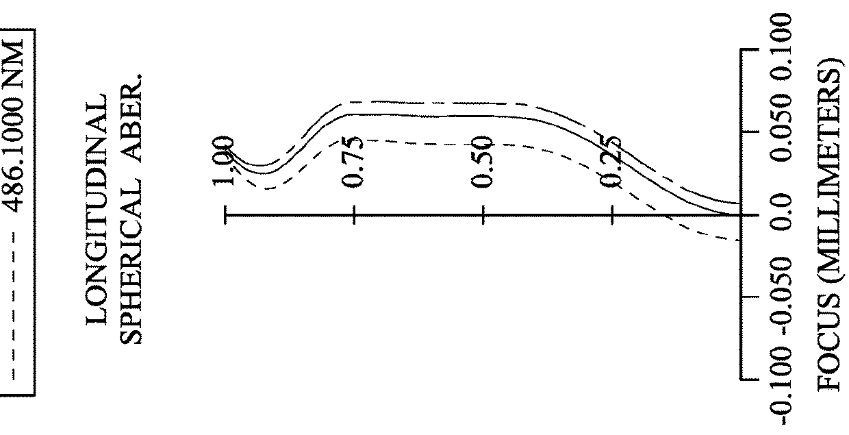
[0088]FIG. 1 is a schematic view of an imaging apparatus according to the 1st embodiment of the present disclosure. FIG. 2A shows spherical aberration curves, astigmatic field curves and a distortion curve of Mode 1 of the imaging apparatus according to the 1st embodiment, and FIG. 2B shows spherical aberration curves, astigmatic field curves and a distortion curve of Mode 2 of the imaging apparatus according to the 1st embodiment, wherein Mode 1 and Mode 2 are two modes of the imaging apparatus at two different focusing conditions, and the detailed conditions are shown in Table 1C below. In FIG. 1, the imaging apparatus includes an image capturing lens assembly (its reference numeral is omitted) and an image sensor 190. The image capturing lens assembly includes, in order from an object side to an image side, a focus tunable component 195, an aperture stop 100, a first lens element 110, a second lens element 120, a third lens element 130, a filter 170 and an image surface 180, and ...
2nd embodiment
[0106]FIG. 3 is a schematic view of an imaging apparatus according to the 2nd embodiment of the present disclosure. FIG. 4A shows spherical aberration curves, astigmatic field curves and a distortion curve of Mode 1 of the imaging apparatus according to the 2nd embodiment, and FIG. 4B shows spherical aberration curves, astigmatic field curves and a distortion curve of Mode 2 of the imaging apparatus according to the 2nd embodiment, wherein Mode 1 and Mode 2 are two modes of the imaging apparatus at two different focusing conditions, and the detailed conditions are shown in Table 2C below. In FIG. 3, the imaging apparatus includes an image capturing lens assembly (its reference numeral is omitted) and an image sensor 290. The image capturing lens assembly includes, in order from an object side to an image side, a focus tunable component 295, an aperture stop 200, a first lens element 210, a second lens element 220, a third lens element 230, a fourth lens element 240, a filter 270 and...
3rd embodiment
[0116]FIG. 5 is a schematic view of an imaging apparatus according to the 3rd embodiment of the present disclosure. FIG. 6A shows spherical aberration curves, astigmatic field curves and a distortion curve of Mode 1 of the imaging apparatus according to the 3rd embodiment, and FIG. 6B shows spherical aberration curves, astigmatic field curves and a distortion curve of Mode 2 of the imaging apparatus according to the 3rd embodiment, wherein Mode 1 and Mode 2 are two modes of the imaging apparatus at two different focusing conditions, and the detailed conditions are shown in Table 3C below. In FIG. 5, the imaging apparatus includes an image capturing lens assembly (its reference numeral is omitted) and an image sensor 390. The image capturing lens assembly includes, in order from an object side to an image side, a focus tunable component 395, an aperture stop 300, a first lens element 310, a second lens element 320, a third lens element 330, a fourth lens element 340, a fifth lens ele...
PUM
 Abstract
Description
Claims
Application Information
 - R&D
- Intellectual Property
- Life Sciences
- Materials
- Tech Scout
- Unparalleled Data Quality
- Higher Quality Content
- 60% Fewer Hallucinations
Browse by: Latest US Patents, China's latest patents, Technical Efficacy Thesaurus, Application Domain, Technology Topic, Popular Technical Reports.
© 2025 PatSnap. All rights reserved.Legal|Privacy policy|Modern Slavery Act Transparency Statement|Sitemap|About US| Contact US: help@patsnap.com