Separation of liquid in droplets and sedimented material enclosed therein

a technology of sedimented material and droplets, which is applied in the field of sedimented material enclosed in droplets and liquid separated in droplets, can solve the problem of not fully developed scientific explanation of this microbial behavior, and achieve the effect of easy removal and no risk of contamination

Active Publication Date: 2018-09-20
BRUKER DALTONIK GMBH & CO KG
View PDF0 Cites 1 Cited by
  • Summary
  • Abstract
  • Description
  • Claims
  • Application Information

AI Technical Summary

Benefits of technology

[0025]The mask is preferably manufactured from a stiff, rigid material. It can be manufactured from profiled or perforated filter paper, non-woven material or cardboard, for example. Rigid materials are particularly suitable for automated procedures for drawing off liquid. Using specially adapted handling devices such as robot arms, the rigid masks can easily be removed from a storage place, clamped into an adapted holder, conveyed to the liquid removal stage and then set down in the required place, and disposed of, if required.
[0026]To produce the masks, it is possible to take a length of the absorbent material, cut off pieces of the mask of a size to suit the desired outer contour of the mask, and then press or cut the predefined pattern of indentations or holes into them, the latter by punching, for example. Particularly if it is to be used in a microbiology laboratory, it is advisable to choose the outer dimensions of the mask such that the liquid removed, together with any microorganisms which may possibly remain suspended in it, cannot penetrate to the outer edge or top of the mask, even when the liquid is completely absorbed, in order that the mask can still be gripped and moved without any risk of contamination.

Problems solved by technology

As yet there is no fully developed scientific explanation for this microbial behavior in a droplet on a flat substrate.

Method used


Image

  • Separation of liquid in droplets and sedimented material enclosed therein
  • Separation of liquid in droplets and sedimented material enclosed therein
  • Separation of liquid in droplets and sedimented material enclosed therein

Examples


Embodiment Construction

[0033]While the invention has been illustrated and explained with reference to a number of different embodiments, those skilled in the art will recognize that various changes in form and detail may be made to it without departing from the scope of the technical teaching as defined in the appended claims.

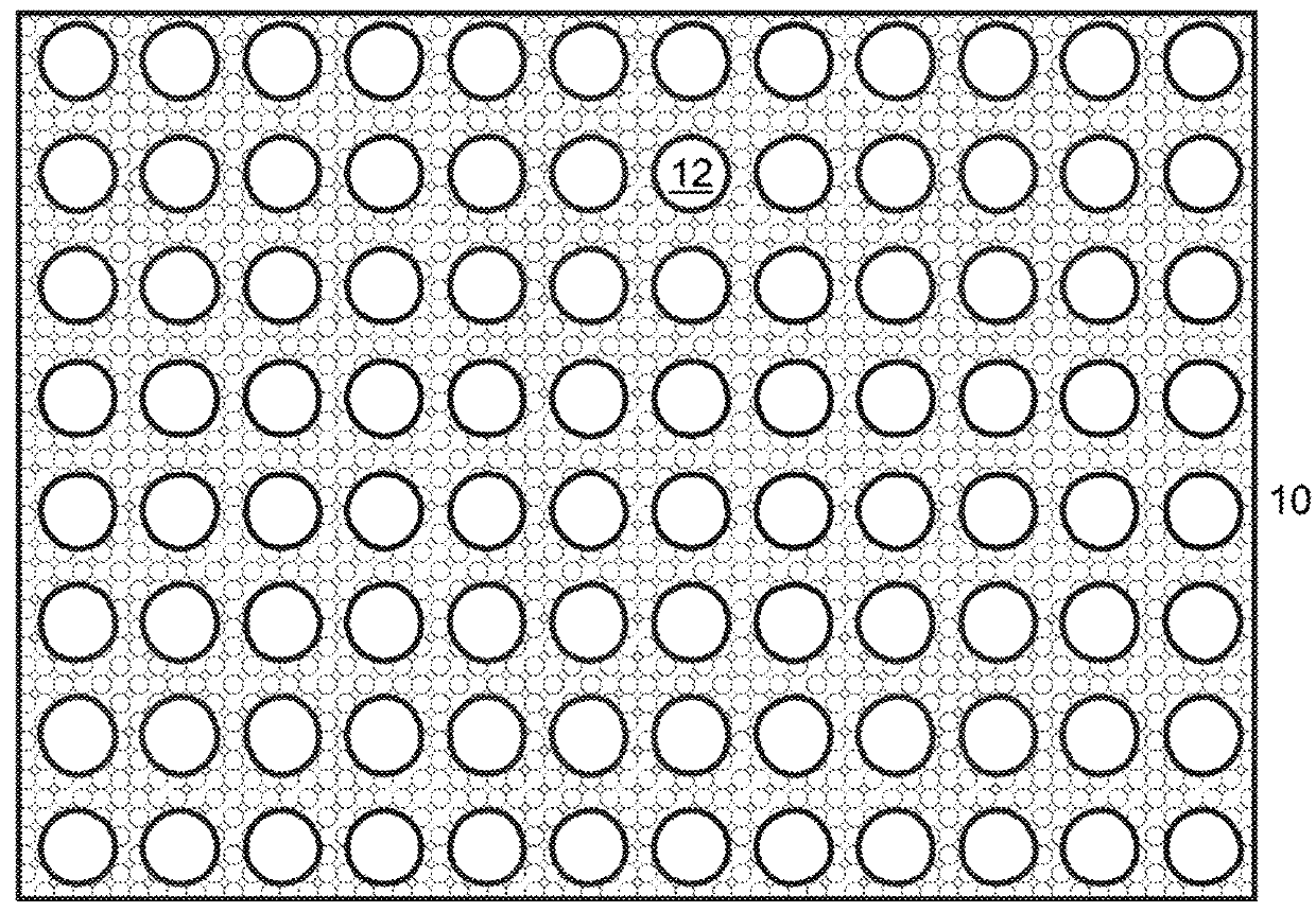
[0034]FIG. 1 depicts a plan view of a mask of rectangular form (10), which has an array of 96 holes (12) arranged in a nine-millimeter grid in an arrangement of eight rows by twelve columns. Smaller (e.g. 48) or larger (e.g. 384) arrays are also conceivable, however. The array can generally correspond to the arrangement of sample spots on a conventional, standardized sample support for ionization by means of matrix assisted laser desorption (MALDI). The dimensions of the mask (10) can be 127.76 mm (length)×85.48 mm (width), corresponding to a microtitration plate, with a thickness of around two to five millimeters.

[0035]FIG. 2A shows an arrangement of equal droplets (14) in a row of ...


PUM

PropertyMeasurementUnit
volumeaaaaaaaaaa
standing timeaaaaaaaaaa
volumesaaaaaaaaaa

Abstract

The invention relates to methods for drawing-off liquid from individual droplets which are in a predefined arrangement on a flat substrate and have sedimented material enclosed in them. A mask of an absorbent material comprising a pattern of indentations or holes which corresponds at least partially to the regular arrangement of the individual droplets, or a stiff, rigid plate of an absorbent material is positioned above the flat substrate in such a way that the droplets come into contact with the absorbent material peripherally so that liquid is drawn off there-into. The invention also relates to a mask of an absorbent material with a substantially rectangular shape which has a predefined pattern of indentations or holes for the purpose of separating liquid and sedimented material enclosed therein.

Description

BACKGROUND OF THE INVENTIONField of the Invention[0001]The invention relates to methods for drawing-off liquid from individual droplets which are in a predefined (especially regular) arrangement on a flat substrate and have sedimented material enclosed in them. The invention also relates to a mask of an absorbent material with a substantially rectangular shape which has a predefined (regular) pattern of indentations or holes for the purpose of separating liquid and sedimented material enclosed therein.Description of the Related Art[0002]There is a need to gently separate liquid from the sedimented material enclosed in it so that as little as possible of the sedimented material is removed together with the liquid in this separation process, while unsedimented (i.e. still suspended) constituents are also to be drawn off with the liquid.[0003]The Prior Art is explained below with reference to a special aspect. This shall not be understood as a limitation, however. Useful further develo...

Claims


Application Information

Patent Timeline
Patent Type & Authority Applications(United States)
IPC IPC(8): H01J49/04B01L3/00
CPCH01J49/0418B01L3/5085B01J2219/00315B01D17/0202B01D21/00G01N1/2813B01D43/00C12Q1/02
Inventor SCHÜRENBERG, MARTINVOSSGRÖNE, ALEXANDER
Owner BRUKER DALTONIK GMBH & CO KG
Why Eureka
Try Eureka