Liquid ejecting device, head unit, and method for controlling liquid ejecting device

Active Publication Date: 2018-09-13
SEIKO EPSON CORP
View PDF4 Cites 0 Cited by
  • Summary
  • Abstract
  • Description
  • Claims
  • Application Information

AI Technical Summary

Benefits of technology

The liquid ejecting device described in this patent can detect residual vibrations caused by three different waveforms. By detecting these vibrations in a specific order, the device can gather more information and accurately determine the characteristics of the residual vibrations. This helps to accurately determine the ejection state of the liquid from the ejecting section, even when there is not a sufficient amount of residual vibration detection period. The method for controlling the device is also described.

Problems solved by technology

Such a liquid ejecting device has a problem in that an abnormal ejection state (in which the liquid cannot be normally ejected from the ejecting section) may occur when the liquid within the cavity has increased in viscosity, or when air bubbles have been formed within the cavity, for example.
When such an abnormal ejection state has occurred, it may be impossible to accurately form a predetermined dot on the recording medium using the liquid ejected from the ejecting section, whereby the quality of the image that is formed by the liquid ejecting device on the recording medium may deteriorate.
When the detection period is short, it is likely that it is difficult to accurately determine the characteristics (e.g., cycle and amplitude) of residual vibrations.
In this case, it is likely that the determination accuracy as to the ejection state based on the characteristics of residual vibrations, deteriorates.

Method used


Image

  • Liquid ejecting device, head unit, and method for controlling liquid ejecting device
  • Liquid ejecting device, head unit, and method for controlling liquid ejecting device
  • Liquid ejecting device, head unit, and method for controlling liquid ejecting device

Examples


first modification

[0240

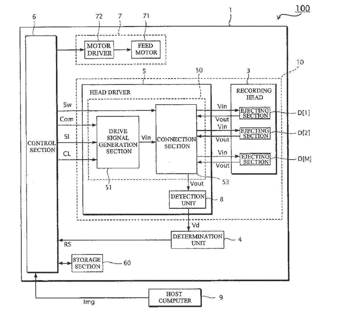
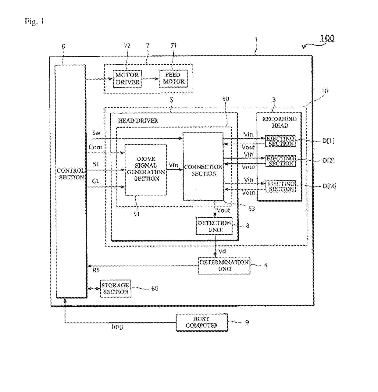
[0241]Although the above embodiments have been described taking an example in which the detection unit 8 detects the residual vibration signal Vout1 in the detection period Td1, detects the residual vibration signal Vout2 in the detection period Td2, and detects the residual vibration signal Vout3 in the detection period Td3, the invention is not limited thereto. It suffices that the detection unit 8 at least detect the residual vibration signal Vout3 in the detection period Td3.

[0242]For example, the detection unit 8 may detect only the residual vibration signal Vout3 without detecting the residual vibration signal Vout1 and the residual vibration signal Vout2. In this case, the connection circuit Ux[m] that corresponds to the ejecting section D[m] designated as the target ejecting section Dtg in one unit period Tu is set to the second connection state in the detection period Td3 within the one unit period Tu, and is set to the first connection state in a period within the one...

second modification

[0244

[0245]Although the above embodiments and modifications have been described taking an example in which the waveform PA11 that changes from the reference potential V0 to the potential Va11 (i.e., first potential) is used as the first waveform, the invention is not limited thereto. It suffices that the first waveform be a waveform that changes from a potential that differs from the first potential to the first potential. The second waveform is not limited to a waveform that changes from the first potential to the second potential. It suffices that the second waveform be a waveform that changes from a potential that differs from the second potential to the second potential. The third waveform is not limited to a waveform that changes from the second potential to the third potential. It suffices that the third waveform be a waveform that changes from a potential that differs from the third potential to the third potential.

third modification

[0246

[0247]Although the above embodiments and modifications have been described taking an example in which the waveform PA1 uses the potential Va1, the potential Va12, and the potential Va13 (reference potential V0) as the holding potential at which the signal is held for a time equal to or longer than a given time, the invention is not limited thereto. The waveform PA1 may also use a potential other than the potential Va11, the potential Va12, and the potential Va13 as the holding potential.

[0248]For example, the waveform PA1 may also use a potential Va14 as the holding potential (see FIG. 23). In the example illustrated in FIG. 23, the potential Va14 is a potential between the potential Va12 and the potential Va13, the waveform PA1 is designed so that the signal is held at the potential Va14 in a period between the end of the detection period Td2 and the start of the detection period Td3. When employing the example illustrated in FIG. 23, the detection unit 8 may detect the residu...


PUM


Abstract

A liquid ejecting device includes: an ejector including: a piezoelectric element displacing corresponding to a drive signal potential; a pressure chamber changing volume corresponding to the piezoelectric element displacement; and a nozzle communicating with the pressure chamber, and ejecting liquid from the pressure chamber; and a detector detecting residual vibrations produced by the ejector after piezoelectric element displacement. The detector detects the residual vibrations in a third period when the drive signal having a drive waveform is supplied to the piezoelectric element. The drive waveform being set to a first potential in a first period, a second potential in a second period, and a third potential in the third period. The volume of the pressure chamber in the second period is smaller than the volume in the first period. The volume of the pressure chamber in the third period is larger than in the second period.

Description

BACKGROUNDTechnical Field[0001]The present invention relates to a liquid ejecting device, a head unit, and a method for controlling a liquid ejecting device.Related Art[0002]A liquid ejecting device such as an inkjet printer is configured so that a liquid (e.g., ink) with which a cavity (pressure chamber) formed in an ejecting section is filled, is ejected by driving (displacing) a piezoelectric element provided to the ejecting section based on a drive signal to form an image on a recording medium. Such a liquid ejecting device has a problem in that an abnormal ejection state (in which the liquid cannot be normally ejected from the ejecting section) may occur when the liquid within the cavity has increased in viscosity, or when air bubbles have been formed within the cavity, for example. When such an abnormal ejection state has occurred, it may be impossible to accurately form a predetermined dot on the recording medium using the liquid ejected from the ejecting section, whereby the...

Claims


Application Information

Patent Timeline
IPC IPC(8): B41J2/045B41J2/14B41J2/165
CPCB41J2/04588B41J2/0451B41J2/04541B41J2/04581B41J2/04596B41J2/14201B41J2/16585B41J2002/14354B41J2/04593B41J2/16579B41J29/38B41J2202/21B41J29/393
Inventor SHINKAWA, OSAMU
Owner SEIKO EPSON CORP
Why Eureka
Try Eureka