
Systems, methods and devices for prosthetic heart valve with single valve leaflet

a prosthetic heart valve and leaflet technology, applied in the field of systems, methods and devices for prosthetic heart valves with single leaflet, can solve the problems of mitral valve regurgitation, failure to properly close, and failure to properly open the valve structur

Pending Publication Date: 2018-09-13
C MEDICAL TECH INC
View PDF2 Cites 17 Cited by
  • Summary
  • Abstract
  • Description
  • Claims
  • Application Information

AI Technical Summary

Benefits of technology

The patent text describes a system for replacing a dysfunctional heart valve with a single valve leaflet. The system includes a device that can be expanded within the heart chamber to position the valve in place. The device has a unique design that allows for easy positioning and adjustment, and can be collapsed for recapture and positional adjustment without needing to fully expand and contract the device. The technical effects of this system include improved accuracy in positioning and reduced risk of complications during heart valve replacement surgery.

Problems solved by technology

These types of conditions may cause the valve structure to either fail to properly open (stenotic failure) and / or fail to close properly (regurgitant).
Mitral valve regurgitation is a specific problem resulting from a dysfunctional mitral valve.
A similar problem may occur when the tricuspid valve weakens or begins to fail.
See e.g., U.S. Pat. No. 4,106,129 (Carpentier), for a procedure that is highly invasive, fraught with patient risks, and requiring not only an extended hospitalization but also a highly painful recovery period.
This self-expanded form also presents problems when, as is often the case, the device is not properly positioned in the first positioning attempt and, therefore, must be recaptured and positionally adjusted.
Collapsing the already expanded device is difficult because the expanded stent or wire network is generally designed to achieve the expanded state which also resists contractive or collapsing forces.
However, known delivery systems, devices and methods still suffer from significant flaws in delivery methodology including, inter alia, positioning and recapture capability and efficiency.
Obviously, there will be cases when native valve has either lost virtually complete functionality before the interventional implantation procedure, or the native valve continues to lose functionality after the implantation procedure.
Such 2-chamber and native annular solutions are unnecessary bulky and therefore more difficult to deliver and to position / recapture / reposition from a strictly structural perspective.
Further, the 2-chamber solutions present difficulties in terms of making the ventricular anchoring and / or tethering connections required to hold position.
Moreover, these solutions interfere with the native valve functionality as described above because the device portions that are disposed within the left ventricle must be routed through the native annulus and / or annular throat and native mitral valve, thereby disrupting any remaining coaptation capability of the native leaflets.
In addition, the 2-chamber solutions generally require an invasive anchoring of some of the native tissue, resulting in unnecessary trauma and potential complication.
A disruption in either papillary muscle in the setting of myocardial injury, can result in dysfunction of either the anterior or posterior leaflet of the mitral valve.
Other mechanisms may result in failure of one, or both of the mitral leaflets.
Other leaflet failures may comprise a more centralized regurgitation jet.
Known prosthetic valve replacements generally comprise leaflets which are arranged to mimic the native valve structure, which may over time become susceptible to similar regurgitation outcomes.

Method used


Image

  • Systems, methods and devices for prosthetic heart valve with single valve leaflet
  • Systems, methods and devices for prosthetic heart valve with single valve leaflet
  • Systems, methods and devices for prosthetic heart valve with single valve leaflet

Examples


Embodiment Construction

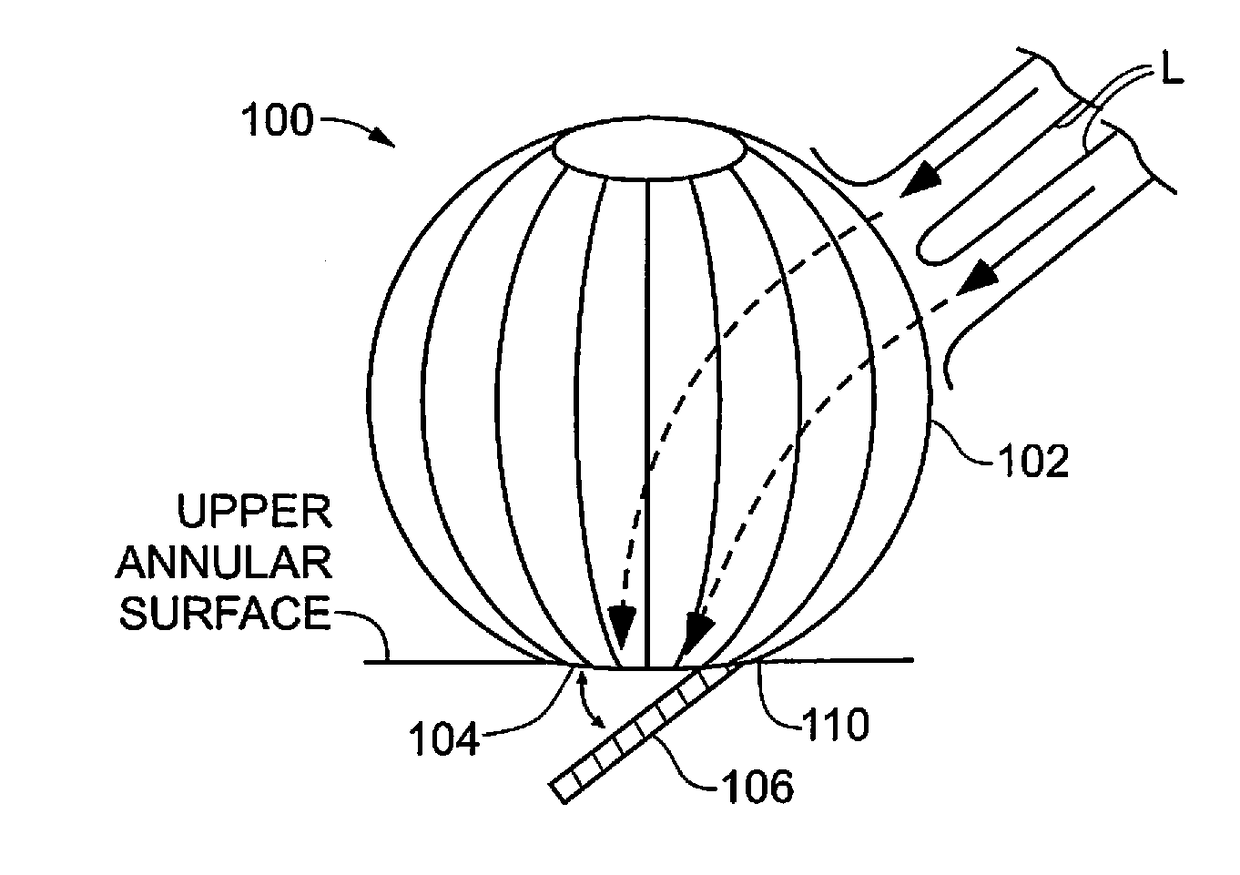
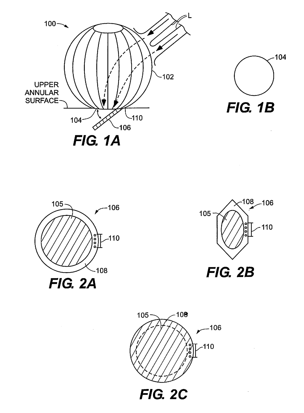
[0034]FIGS. 1A and 1B provides an exemplary expanded prosthetic valve device 100 adapted for implantation within a heart chamber, e.g., the left atrium. An anchoring portion 102 is shown with a wire, e.g., a stent, construction that may be open, or at least partially open, when expanded within an exemplary left atrium. Anchoring portion 102 may be hollow and may provide a flow channel, shown in dashed lines at 103 in FIG. 1A, therethrough for blood flowing into the open wire construction of the anchoring portion 102 from the left pulmonary veins L into the left atrium where the device 100 is expanded and positioned for implantation. A lower section of anchoring portion 102, that is the section of the anchoring portion 102 that is located below the incoming blood flow points at the left pulmonary veins L, may be covered by fabric and / or tissue, either on the luminal side, the abluminal side, or on both the luminal and abluminal sides of the anchoring portion 102 to help channel the i...


PUM


Abstract

Devices and methods for supplementing and / or replacing native cardiac valve functionality, e.g., the mitral valve with a single prosthetic leaflet. An exemplary device is directed to dysfunctional mitral valves. In some cases, the entire device, including the single prosthetic leaflet, will be arranged entirely above the dysfunctional mitral valves and, therefore, disposed entirely within the left atrium. In other cases, the valve support and / or single prosthetic leaflet may extend a distance into the annulus between the left atrium and left ventricle. In some cases, the device will not physically interact with the native leaflets. In other cases, the device may physically interact with the native leaflets.

Description

CROSS-REFERENCE TO RELATED APPLICATIONS[0001]This application claims the benefit of U.S. Provisional Application Ser. No. 62 / 468,112, filed Mar. 7, 2017, and titled SYSTEMS, METHODS AND DEVICES FOR PROSTHETIC HEART VALVE WITH SINGLE VALVE LEAFLET, the entire contents of which are incorporated herein by reference.STATEMENT REGARDING FEDERALLY SPONSORED RESEARCH OR DEVELOPMENT[0002]Not ApplicableINCORPORATION BY REFERENCE[0003]All references, including but not limited to publications, patent applications and patents mentioned in this specification are hereby incorporated by reference to the same extent and with the same effect as if each reference was specifically and individually indicated to be incorporated by reference.BACKGROUND OF THE INVENTIONField of the Invention[0004]The invention relates to supplementing and / or replacing native heart valve leaflet function.Description of the Related Art[0005]The human heart comprises four chambers and four heart valves that assist in the for...

Claims


Application Information

Patent Timeline
IPC IPC(8): A61F2/24
CPCA61F2/2445A61F2/2409A61F2/2463A61F2220/0091A61F2/2418A61F2/2412A61F2230/0071
Inventor CHAMBERS, JEFFREY W.KUMAR, SARAVANA B.HIGGINS, JOSEPH P.THATCHER, ROBERT J.DIEDERING, JASON S.STONE, JEFFREY R.
Owner C MEDICAL TECH INC
Learn More