
Method and arrangement for the secure display of information

Inactive Publication Date: 2018-09-06
SIOPTICA
View PDF4 Cites 45 Cited by
  • Summary
  • Abstract
  • Description
  • Claims
  • Application Information

AI Technical Summary

Benefits of technology

The invention describes a way to securely display information using a method and arrangement that can be implemented at low cost in the production of goods. The goal is to reduce visual fatigue and make the display brighter, while also minimizing the amount of power consumed. The approach can be applied to both self-luminous and non-triggerable display types, and the use of passive light scattering instead of louves that contain triggerable layers can further reduce haze. Additionally, optically transparent material can be used between adjacent louves to create a robust construction. Overall, the technical effects of the invention revolve around improving the quality and efficiency of information display.

Problems solved by technology

However, such foils cannot be switched over between a narrow and a wide viewing angle range; rather, they have to be applied and removed manually.
Here, however, handling the filter involves its mechanical, i.e., manual attachment and removal, which is a disadvantage.
Moreover, light loss in the protected mode is very high, so that this privacy filter can hardly be used in high-brightness environments.
Here again, the technical complexity and costs involved are high.
As in the film filters described above, the light loss is excessive here, and technical implementation is rather complex and expensive.
This solution is expensive, though; in addition it causes a great loss in brightness, as in the approaches described above.
Whereas this solution is attractive for LCD panels, it is unfit to offer a solution for self-luminous displays such as, e.g., OLEDs.
As a drawback, PDLC crystals require relatively high alternating voltages of several tens of volts to switch to the transparent mode.
Moreover, to obtain sufficiently strong scattering effects for the private mode, the PDLC crystals have to be quite some thickness, which results in an attenuation of the light transmitted in the transparent mode, so that, in this configuration, one has to reckon with visible structures on the screen that disturb the image appearance.
The disadvantage here, in particular, is the diminished resolution due to the effects of the lenses.
Drawbacks are the high intricacy of fabrication and the light loss.
However, this requires the optical component to be arranged behind the image display device, which is impracticable in many cases.
With the methods and arrangements known in prior art, the provision of a capability to switch between a private, protected mode with a restricted viewing angle range and a public, unprotected mode with a wide viewing angle range as a rule has the result that the brightness of the basic display screen is markedly decreased and / or the method is inapplicable to self-luminous types of display screens and / or one of the two modes, if not both, consume extra power.
In addition, manufacture is, in most cases, technically complicated and, thus, expensive.

Method used


Image

  • Method and arrangement for the secure display of information
  • Method and arrangement for the secure display of information
  • Method and arrangement for the secure display of information

Examples


Embodiment Construction

[0015]Therefore, the problem underlying the invention is to develop a method and an arrangement for the secure presentation of information, with the arrangement and the method intended to be implementable in lot production at affordable cost. Added aims are to ensure that the brightness of the basic display screen is reduced but insignificantly or not at all, that the engineering approach is applicable also to self-luminous display types, and that, in either mode, any extra power consumption is negligible.

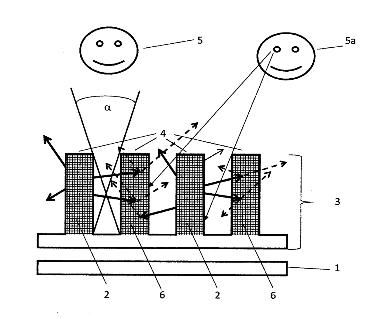
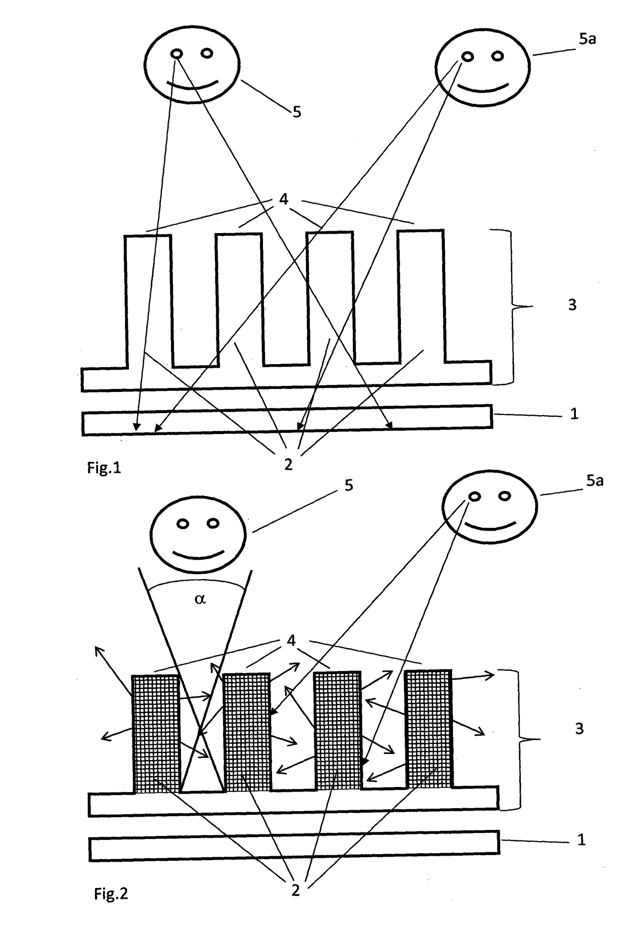
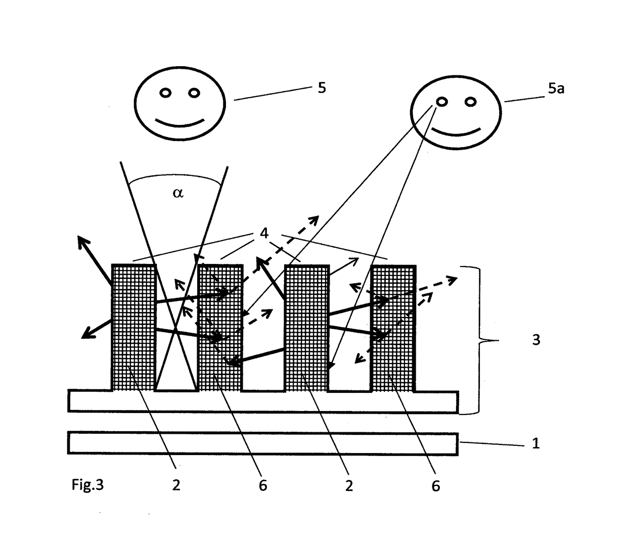
[0016]According to the invention, the problem is solved by a method for operating a display screen in at least two operating modes, i.e. B1 for a free viewing mode and B2 for a restricted viewing mode, comprising the following steps:[0017]Arrangement of a switchable optical element immediately in front of a display screen as seen in a viewer's viewing direction, the said optical element ensuring switching between the at least two operating modes B1 and B2,[0018]presentation of an i...


PUM


Abstract

A method to operate a display screen D in at least two operating modes, B1 for a free viewing mode and B2 for a restricted viewing mode, comprising the following steps: arrangement of a switchable optical element immediately in front of a display screen as seen in a viewer's viewing direction, the said optical element ensuring switching between the at least two operating modes B1 and B2, presentation of an image content on the display screen, wherein the optical element contains a multitude of louvers, and wherein the optical effect of the louvers can be changed between transparent (B1) and luminous (B2) due to the fact that at least every twentieth louver contains triggerable layers that can be switched to be either transparent or brightly self-luminous.

Description

PRIORITY CLAIM[0001]The present application is a National Phase entry of PCT Application No. PCT / EP2016 / 001538, filed Sep. 13, 2016, which claims priority from German Patent Application Number 102015011933.8, filed Sep. 14, 2015, the disclosures of which are hereby incorporated by reference herein in their entirety.FIELD OF THE INVENTION[0002]In the development of flat-panel displays, the recent years have seen substantial efforts concentrated on increasing a viewer's viewing angle. Frequently, however, there are situations in which an excessive angular viewing range is a disadvantage, as, for example, during the entry of personal identification numbers (PINs) into the display screens of automated teller machines (ATMs). Also, applications enabling bank transactions to be conducted or other private particulars or sensitive data to be displayed are increasingly available for mobile devices such as tablet PCs, cell phones or even notebooks. For these purposes, the users of such device...

Claims


Application Information

Patent Timeline
IPC IPC(8): G02F1/13G09G3/3208H01L27/32G02F1/1347
CPCG02F1/1323G09G3/3208H01L27/3232G02F1/13476G02B2006/12097G09G2358/00G02F2001/133562G02F2203/62G09G2320/068B32B3/085B32B3/30H04N5/72G02F2201/15G02F2201/44G02F2202/02G02F2203/01G02F2203/03G09G2300/023B32B2307/412B32B2307/422B32B2457/20B32B2551/00G09G5/00G09G2320/0261G09G2320/028G09G2354/00G09G3/20G02F1/133562H10K59/50H10K2102/3031
Inventor KLIPPSTEIN, MARKUSSCHWARZ, JUERGEN
Owner SIOPTICA
Learn More