
Multiple linked list data structure

a data structure and linked list technology, applied in the field of linked list data structure, can solve the problems of active requestors not being able to access the storage resources dedicated to idle requestors, inefficient resource usage, and multiple requestors consuming an appreciable amount of on-die area

Active Publication Date: 2018-08-30
ATI TECH INC
View PDF8 Cites 2 Cited by
  • Summary
  • Abstract
  • Description
  • Claims
  • Application Information

AI Technical Summary

Benefits of technology

The present invention relates to a buffer for storing information during software application processing. The buffer uses multiple entries for storing various information, and each entry has its own dedicated buffer entry. However, using multiple buffers for different requestors can consume a lot of on-die area and power, and the allocation of buffer entries is not efficient. To address this, the invention proposes a single buffer that can be dynamically allocated to different requestors using multiple linked lists. The buffer can be accessed using a single search operation, but there is a trade-off between latency and performance. The invention also provides methods for accessing the buffer efficiently and maintaining information of pending operations. Overall, the invention improves the efficiency and flexibility of the buffer for storing information during software application processing.

Problems solved by technology

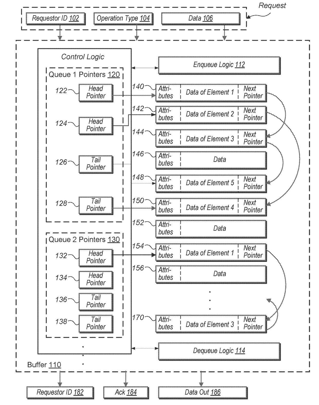
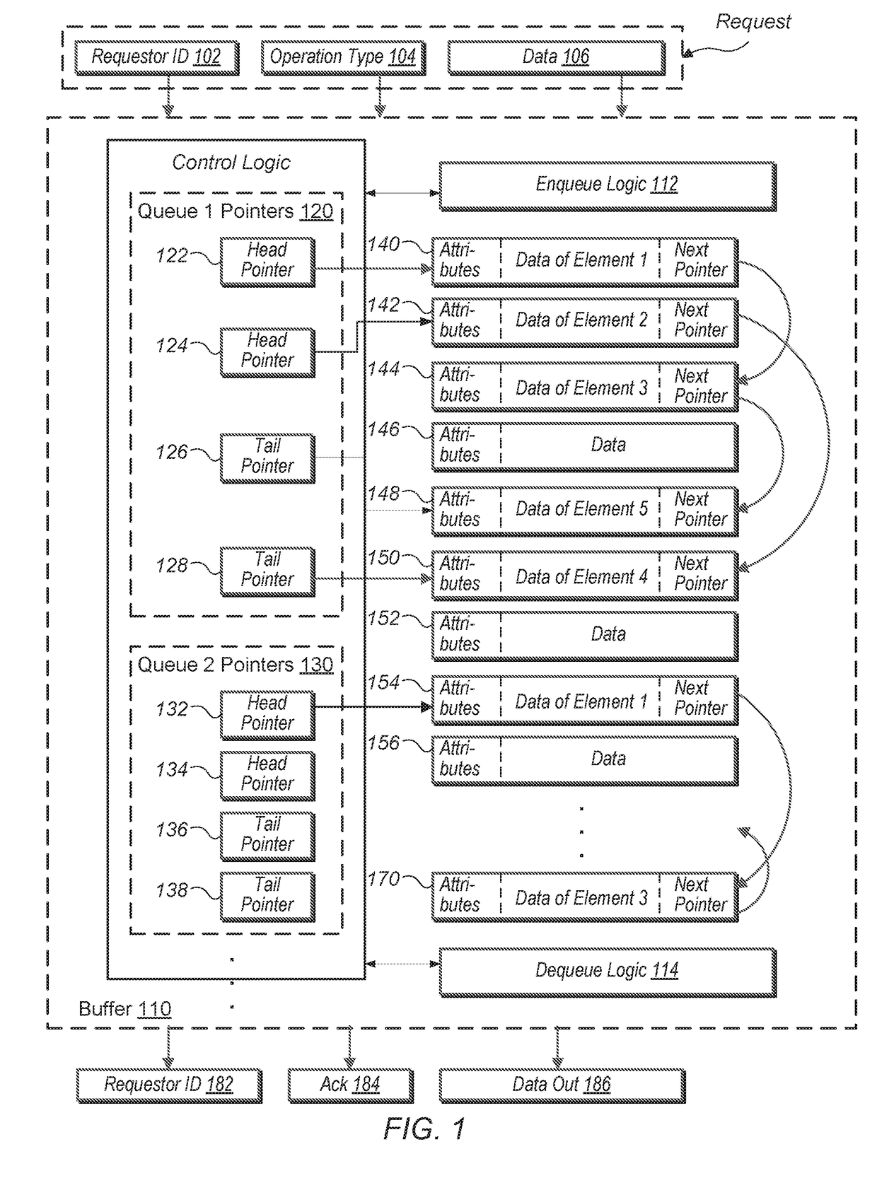
However, with multiple requestors, providing a separate buffer for each of the multiple requestors consumes an appreciable amount of on-die area, especially as each of the number of requestors and the number of buffer entries increase.
In addition, the resource usage becomes inefficient when one or more requestors are relatively idle while other requestors are active.
The active requestors are unable to access the storage resources dedicated to the idle requestors.
Using a single buffer divided into portions, each portion being dedicated to one of the multiple requestors, has the same disadvantages regarding on-die area and inefficient usage of resources.
CAM match comparisons use dynamic logic which consumes a relatively high amount of power as well as affects the processor's clock period.
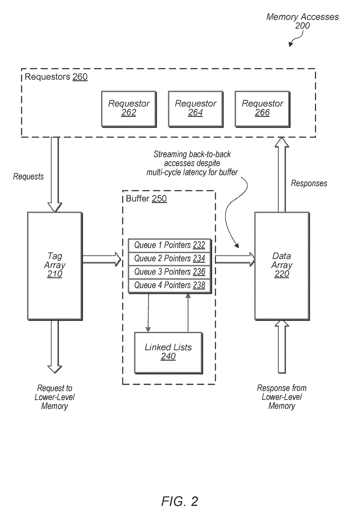
When the latency of accessing the next pointer exceeds a clock cycle, it is no longer possible to stream accesses of the entries in back-to-back clock cycles.
Thus, performance degrades.

Method used


Image

  • Multiple linked list data structure
  • Multiple linked list data structure
  • Multiple linked list data structure

Examples


Embodiment Construction

[0013]In the following description, numerous specific details are set forth to provide a thorough understanding of the present invention. However, one having ordinary skill in the art should recognize that the invention might be practiced without these specific details. In some instances, well-known circuits, structures, and techniques have not been shown in detail to avoid obscuring the present invention. Further, it will be appreciated that for simplicity and clarity of illustration, entries shown in the figures have not necessarily been drawn to scale. For example, the dimensions of some of the entries are exaggerated relative to other entries.

[0014]Methods and systems for maintaining information of pending operations are contemplated. A buffer uses multiple entries for the storage of a variety of information during processing of software applications. Requests, results or responses, changing status information for instructions during intermediate processing steps, and so on are ...


PUM


Abstract

A system and method for maintaining information of pending operations are described. A buffer uses multiple linked lists implementing a single logical queue for a single requestor. The buffer maintains multiple head pointers and multiple tail pointers for the single requestor. Data entries of the single logical queue are stored in an alternating pattern among the multiple linked lists. During the allocation of buffer entries, the tail pointers are selected in the same alternating manner, and during the deallocation of buffer entries, the multiple head pointers are selected in the same manner.

Description

BACKGROUNDDescription of the Relevant Art[0001]Modern microprocessors buffer a variety of information during processing of software applications. Requests, results or responses, changing status information for instructions during intermediate processing steps of the instructions, and so on are stored in buffers. In some embodiments, designers determine an ideal number of buffer entries for a requestor which balances performance with on-die area and power consumption. However, with multiple requestors, providing a separate buffer for each of the multiple requestors consumes an appreciable amount of on-die area, especially as each of the number of requestors and the number of buffer entries increase.[0002]In addition, the resource usage becomes inefficient when one or more requestors are relatively idle while other requestors are active. The active requestors are unable to access the storage resources dedicated to the idle requestors. Using a single buffer divided into portions, each ...

Claims


Application Information

Patent Timeline
IPC IPC(8): G06F13/16
CPCG06F13/1673G06F13/1642G06F5/06G06F2205/064G06F5/065
Inventor MIRZA, JIMSHEDMA, QIAN
Owner ATI TECH INC
Learn More