
Backlight module and display device

a backlight module and display device technology, applied in the field of display, can solve problems such as light waste, and achieve the effect of reducing light waste and effectively utilizing light energy

Active Publication Date: 2018-08-02
BOE TECH GRP CO LTD +1
View PDF2 Cites 1 Cited by
  • Summary
  • Abstract
  • Description
  • Claims
  • Application Information

AI Technical Summary

Benefits of technology

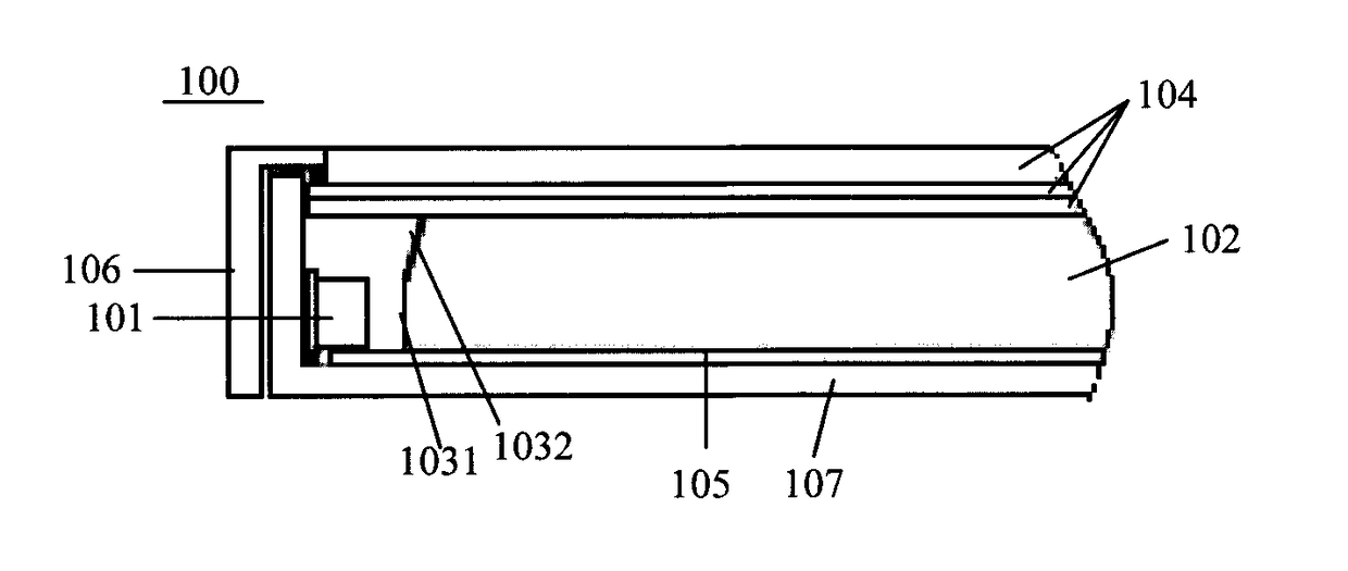
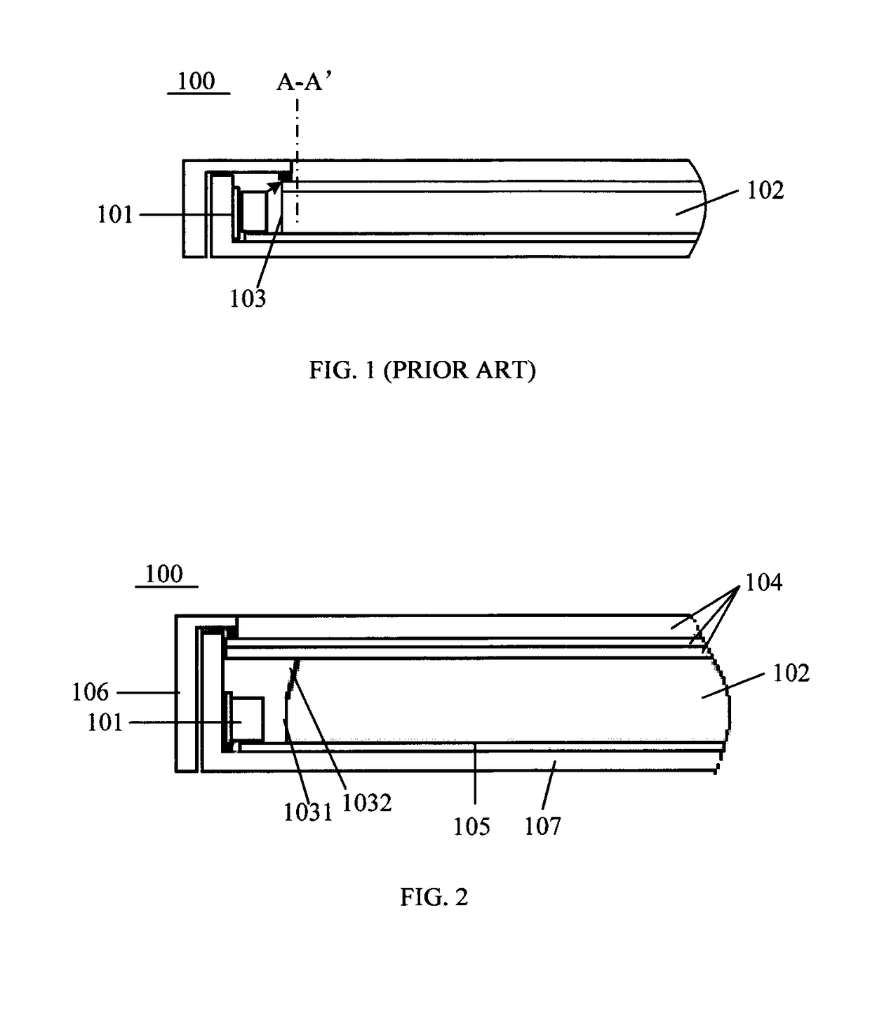
This patent describes a backlight module and display device that can improve the use of light energy and reduce waste. It does this by using a reflecting surface above the light guide plate to capture and reflect light that cannot be directly incident into the guide plate. This reflected light is then utilized by the display panel, improving the energy utilization ratio and reducing dark regions on the display. The result is a narrower bezel or even a bezelless display.

Problems solved by technology

Since the light source 101 generally has a certain light emitting angle, for example, some light emitting electrode (LED) light sources have a light emitting angle of up to 120° or more, only the light in the middle region may be incident into the light guide plate 102, while the light in the edge regions cannot be incident into the light guide plate 102, thereby resulting in a waste of light energy.

Method used


Image

  • Backlight module and display device
  • Backlight module and display device
  • Backlight module and display device

Examples


Embodiment Construction

[0023]Exemplary embodiments will now be described more fully with reference to the accompanying drawings.

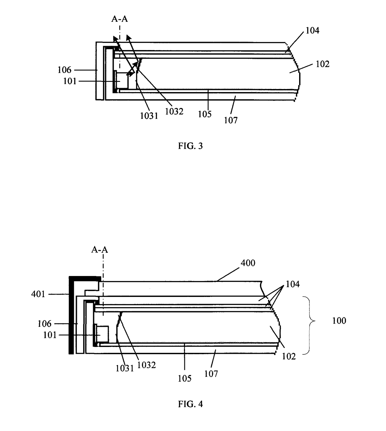
[0024]An embodiment of the present disclosure provides a backlight module. The backlight module includes a light source and a light guide plate, the light source being provided on at least one side of the light guide plate, aside of the light guide plate facing the light source including a light receiving surface facing the light source and a light reflecting surface above the light receiving surface, wherein an angle formed by the light receiving surface and the light reflecting surface in a direction toward inside of the light guide plate is an obtuse angle.

[0025]In this embodiment, when the backlight module provided by this embodiment is applied to the display device, at least a part of light that is not incident into the light guide plate may be reflected to a region of the display panel located above the light source, so as to be utilized by the display panel, thereby reduci...


PUM

PropertyMeasurementUnit
angleaaaaaaaaaa
angleaaaaaaaaaa
light emitting angleaaaaaaaaaa

Abstract

Embodiments of the present disclosure relate to a backlight module and a display device. The backlight module includes a light source and a light guide plate, the light source provided on at least one side of the light guide plate, wherein a side of the light guide plate facing the light source includes a light receiving surface facing the light source and a light reflecting surface above the light receiving surface, wherein an angle formed by the light receiving surface and the light reflecting surface in a direction toward inside of the light guide plate is an obtuse angle. According to the backlight module and the display device provided by the present disclosure, light waste may be reduced and the utilization ratio of light energy may be improved.

Description

CROSS REFERENCE TO RELATED APPLICATIONS[0001]This patent application is a National Stage Entry of PCT / CN2017 / 071141 filed on Jan. 13, 2017, which claims the benefit and priority of Chinese Patent Application No. 201620415683.1 filed on May 10, 2016, the disclosures of which are incorporated herein in their entirety as a part of the present application.BACKGROUND[0002]Embodiments of the present disclosure relate to the technical field of display, and specifically, to a backlight module and a display device.[0003]In a liquid crystal display device, since liquid crystals themselves do not emit light, it is necessary to provide a light emitting source, such as a backlight module, on the light incident side of a liquid crystal display panel to realize the display function of the liquid crystal display device. The function of the backlight module is to provide the display panel with an area source which has high illuminance and uniform, so that the display panel may display images properl...

Claims


Application Information

Patent Timeline
Patent Type & Authority Applications(United States)
IPC IPC(8): G02F1/1335F21V8/00
CPCG02F1/133602G02B6/0011G02F2001/3505G02B6/0031G02B6/0035G02B6/005G02F1/3505G02B6/00
Inventor ZHENG, HUIZHANG, MINGHUISUN, HANYAN
Owner BOE TECH GRP CO LTD
Learn More