Pouring Container for Storing Pourable Foodstuffs
- Summary
- Abstract
- Description
- Claims
- Application Information
AI Technical Summary
Benefits of technology
Problems solved by technology
Method used
Image
Examples
Embodiment Construction
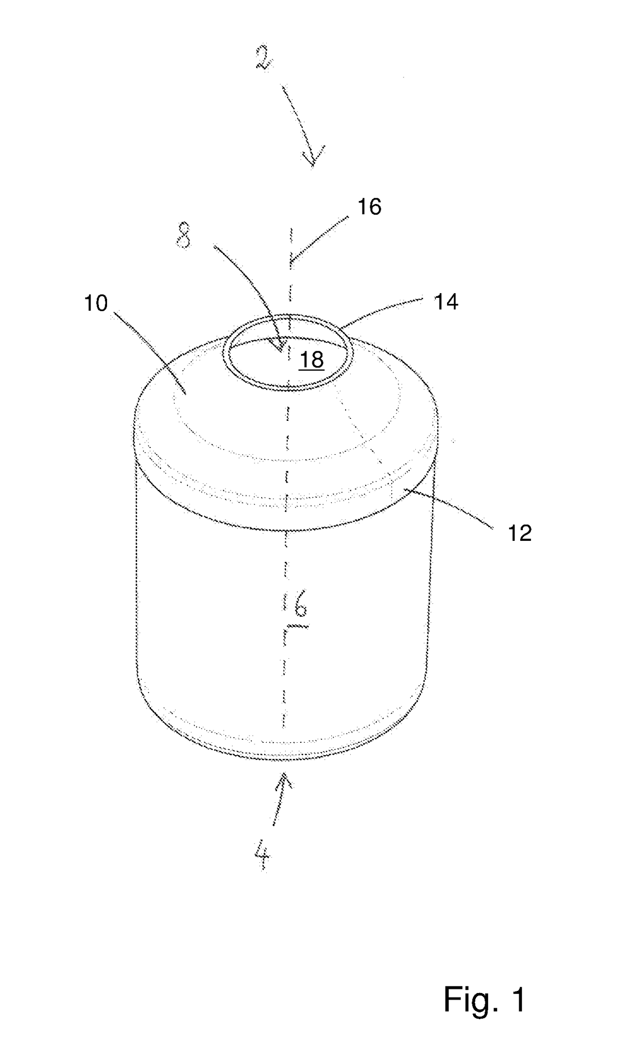
[0031]FIG. 1 illustrates a pouring container 2 in a view obliquely from above. The pouring container 2 has a base 4 with a side wall 6. Toward the top, the pouring container 2 is opened by way of the upper opening 8, which is bounded by the cuff 10.
[0032]The cuff 10 has a first end by way of which the cuff 10 is connected to the side wall 6. The second end of the cuff 10 bounds the opening 8. The cuff 10 consists of an elastic material which makes it possible for the cuff 10 to be able to be pushed with its second end 14 into the storage chamber 18 along the longitudinal axis 16 and moved back out again into the pulled-out position illustrated in FIG. 1.
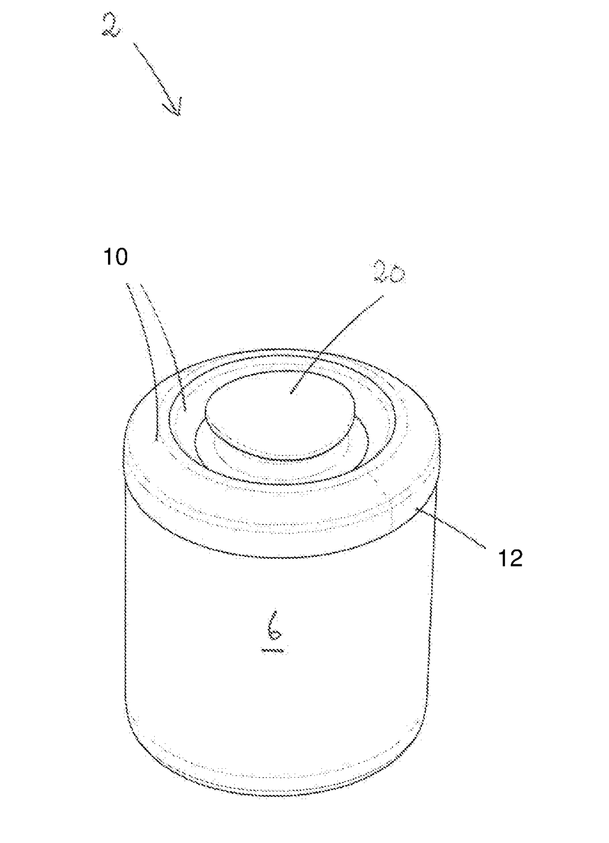
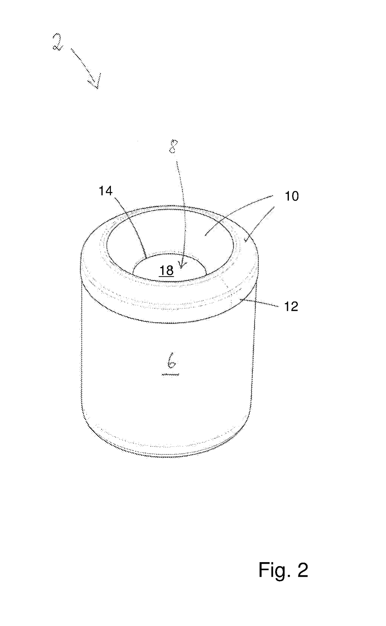
[0033]FIG. 2 shows the pouring container 2 with a cuff 10 which has been pushed into the storage chamber 18. It is apparent from comparing the cuff 10 as is illustrated in FIGS. 1 and 2 that the cuff 10 forms a pouring funnel in the position illustrated in FIG. 1, while it creates a filling funnel in the position illustrated in FIG. ...
PUM
| Property | Measurement | Unit |
|---|---|---|
| Thickness | aaaaa | aaaaa |
| Transparency | aaaaa | aaaaa |
Abstract
Description
Claims
Application Information
 - R&D
- Intellectual Property
- Life Sciences
- Materials
- Tech Scout
- Unparalleled Data Quality
- Higher Quality Content
- 60% Fewer Hallucinations
Browse by: Latest US Patents, China's latest patents, Technical Efficacy Thesaurus, Application Domain, Technology Topic, Popular Technical Reports.
© 2025 PatSnap. All rights reserved.Legal|Privacy policy|Modern Slavery Act Transparency Statement|Sitemap|About US| Contact US: help@patsnap.com


