Artificial christmas tree

Inactive Publication Date: 2018-07-26
TSAI GEORGE
View PDF10 Cites 1 Cited by
  • Summary
  • Abstract
  • Description
  • Claims
  • Application Information

AI Technical Summary

Benefits of technology

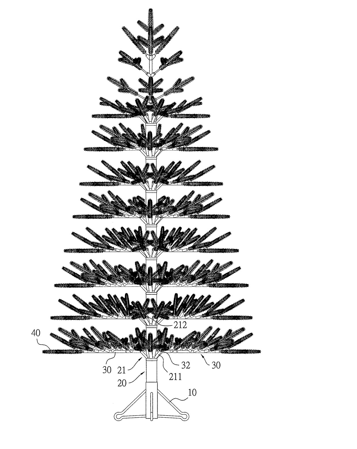
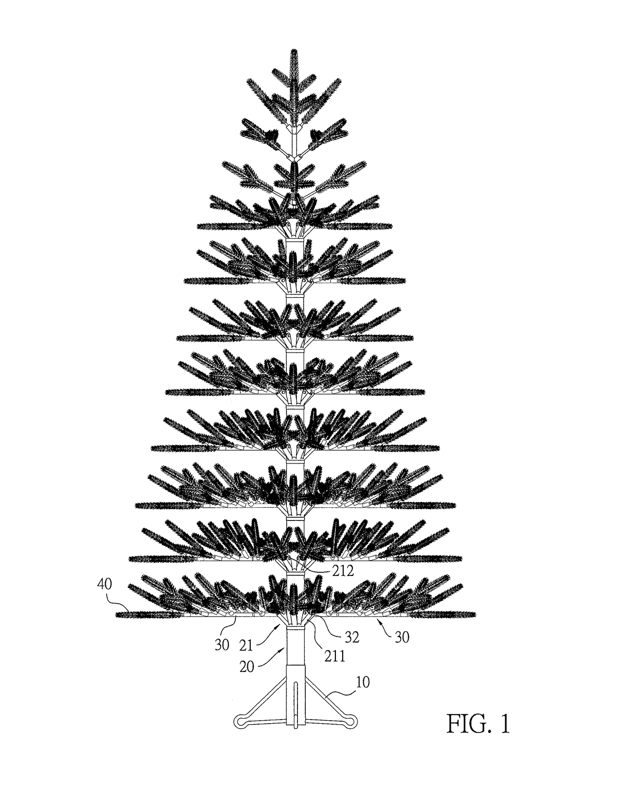
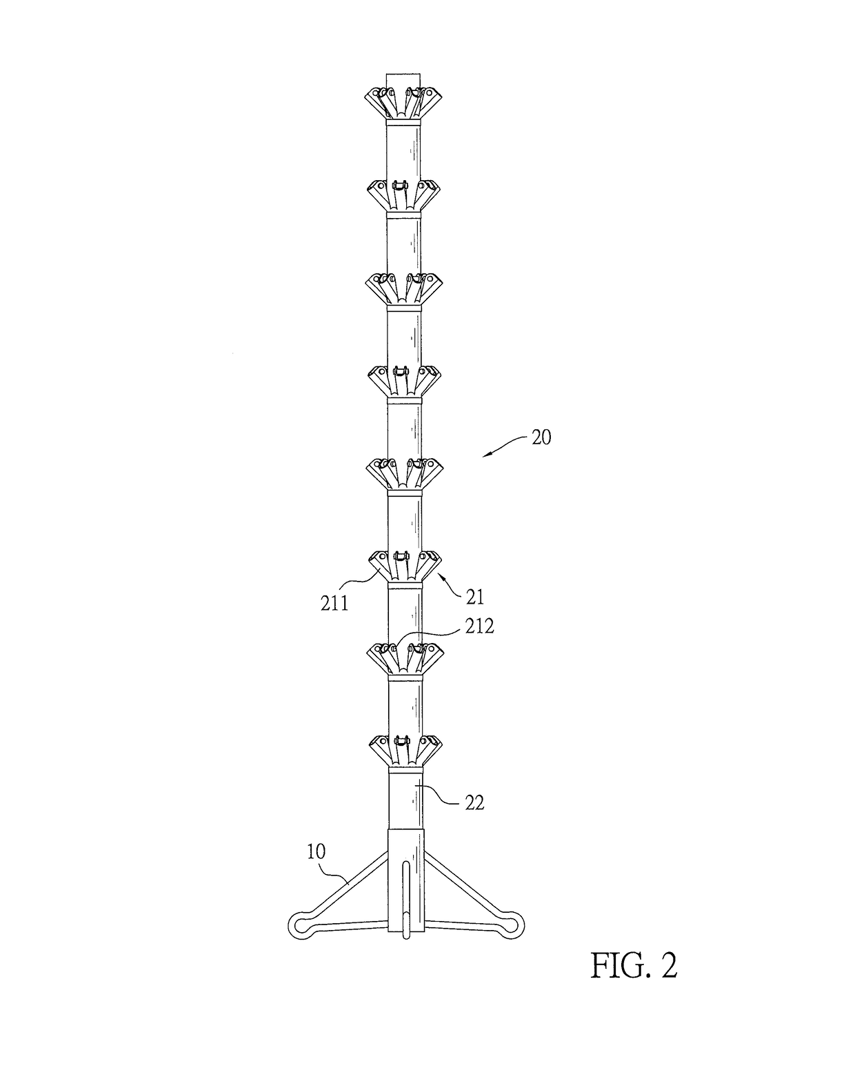
The present invention provides an artificial Christmas tree with multiple branch holders mounted along a longitudinal direction of the trunk and the leaves spread out after mounted on corresponding branches to achieve a simple and easy assembly and three-dimensional spatial perception to viewers. The mounting ears of adjacent two of the branch holders are alternately arranged for exhibiting the artificial Christmas tree with three-dimensional spatial perception to viewers. The included angle between each leafstalk seat and a corresponding branch ensures the leaves to be positioned at optimal position and orientation. The resilient metal wire inside each leaf facilitates the leaf to be flexible and bendable, rendering a small size beneficial to lower warehousing and storage costs when subject to a compression force and a restored shape after the compression force is gone.

Problems solved by technology

Despite the availability of standard operation procedures for assembly of the artificial Christmas trees, under the circumstance that aesthetic judgment varies from person to person and product capacity is a major manufacturing concern, consistent and optimal shape of the artificial Christmas trees is hard to get.
After consumers receive and unpack the purchased artificial Christmas trees, tree leaves and branches of the artificial trees appear to be folded and distorted, giving a tree structure much less than expected by the consumers.
Even though manufacturers of the artificial Christmas trees stress that the artificial Christmas trees may be made of steel wire, which is more rigid and less damage-prone, it is inevitable that the artificial Christmas trees eventually become distorted due to the weight and poor elasticity of the steel wires.

Method used


Image

  • Artificial christmas tree
  • Artificial christmas tree
  • Artificial christmas tree

Examples


fifth embodiment

[0062]With reference to FIGS. 16 and 16A, a leaf 40A combined with a corresponding leafstalk seat 31A is shown, and the present embodiment differs from the foregoing embodiments in the engagement structure of the leaves 40A and the leafstalk seats 31A. Each leafstalk seat 31A has two lateral channels 3111A inwardly formed in the leafstalk seat 31A in a longitudinal direction from the free end to the fixed end of the leafstalk seat 31A and extending along two opposite lateral directions of the leafstalk seat 31A passing through the recess 311A within a range inside the peripheral wall of the leafstalk seat 31A, and being shorter than the recess 311A in depth. The insertion end 41A of each leaf 40A has two raised ribs 411A oppositely formed on a peripheral wall of the insertion end 41A to correspond to the two respective lateral channels 3111A of a corresponding leafstalk seat 31A. The insertion end 41A of each leaf 40A engages the recess 311A of a corresponding leafstalk seat 31A wit...

sixth embodiment

[0063]With reference to FIGS. 17 and 17A, a leaf 40B combined with a corresponding leafstalk seat 31B is shown, and the present embodiment differs from the foregoing embodiments in the engagement structure of the leaves 40B and the leafstalk seats 31B. Each leafstalk seat 31B has two lateral channels 3111B inwardly formed in the leafstalk seat 31B in a longitudinal direction from the free end to the fixed end of the leafstalk seat 31B and formed through the peripheral wall of the leafstalk seat 31B along two opposite lateral directions of the leafstalk seat 31B passing through the recess 311B, and being shorter than the recess 311B in depth. The insertion end 41B of each leaf 40B has two raised ribs 411B oppositely formed on a peripheral wall of the insertion end 41B to correspond to the two respective lateral channels 3111B of a corresponding leafstalk seat 31B. The insertion end 41B of each leaf 40B engages the recess 311B of a corresponding leafstalk seat 31B with the two raised ...

seventh embodiment

[0064]With reference to FIGS. 18 and 18A, a leaf 40C combined with a corresponding leafstalk seat 31C is shown, and the present embodiment differs from the foregoing embodiments in the engagement structure of the leaves 40C and the leafstalk seats 31C. The insertion end 41C of each leaf 40C has a bulged portion 411C annularly formed around a peripheral wall of the insertion end 41C. Each leafstalk seat 31C has a groove 3111C annularly formed in an inner wall surrounding the recess 311C of the leafstalk seat 31C, and corresponding to and engaging the groove 3111C of the leafstalk seat 31C.

[0065]With reference to FIGS. 19 and 19A, an eighth embodiment of a leaf 40D combined with a corresponding leafstalk seat 31D is shown, and the present embodiment differs from the first embodiment in that each leaf 40D has a round hook 43D forming on a bottom end of the leaf 40D and each branch has multiple leafstalk seats 31D and multiple leaf holders 34D corresponding to the multiple leafstalk sea...


PUM


Abstract

An artificial Christmas tree includes a foot stand, a trunk, multiple branches and multiple leaves. One end of the trunk is connected with the foot stand. The trunk has multiple branch holders. Each branch is formed by sheathing plastic around an iron wire and is flexible and bendable. One end of each branch is connected with a corresponding branch holder of the trunk and each branch has multiple leafstalk seats formed around a periphery of the branch for corresponding leaves to be mounted on the leafstalk seats. Each leaf has a resilient metal wire sheathed by plastic and has multiple leaflets formed on the sheathed metal wire. As the leaves can be short or long and can be sequentially spread out after mounted on corresponding branches, a Christmas tree structure with simple and easy assembly and three-dimensional spatial perception to viewers can be attained.

Description

BACKGROUND OF THE INVENTION1. Field of the Invention[0001]The present invention relates to an artificial Christmas tree and, more particularly, to an artificial Christmas tree rendering increased ease and convenience in assembly and shipment of the artificial Christmas tree and quick shape restorability after the artificial Christmas tree is unpacked.2. Description of the Related Art[0002]In view of its simple assembly, complete and beautiful tree structure, and easy storage and relocation, undoubtedly, artificial Christmas tree is one of the most indispensable decorations during the Christmas holiday season. To give an artificial Christmas tree a natural and aesthetically appealing look, tree leaves are supposed to be correctly positioned and oriented as desired.[0003]However, tree leaves of artificial Christmas trees available in the market must be manually adjusted by workers in the factory in terms of location and orientation of the tree leaves before shipment. Despite the avail...

Claims


Application Information

Patent Timeline
IPC IPC(8): A47G33/06
CPCA47G33/06
Inventor TSAI, GEORGE
Owner TSAI GEORGE
Why Eureka
Try Eureka