Three-way ball valve
A technology for three-way ball valves and spheres, which is applied to multi-way valves, valve devices, cocks including cut-off devices, etc., which can solve the problems of increasing the installation difficulty and cost of three-way ball valves, increasing the weight of three-way ball valves, and large outer diameters of balls, etc. problems, to achieve the effect of reducing volume and weight, simple and easy assembly and disassembly, and stable and continuous driving
- Summary
- Abstract
- Description
- Claims
- Application Information
AI Technical Summary
Problems solved by technology
Method used
Image


Examples
Embodiment 1
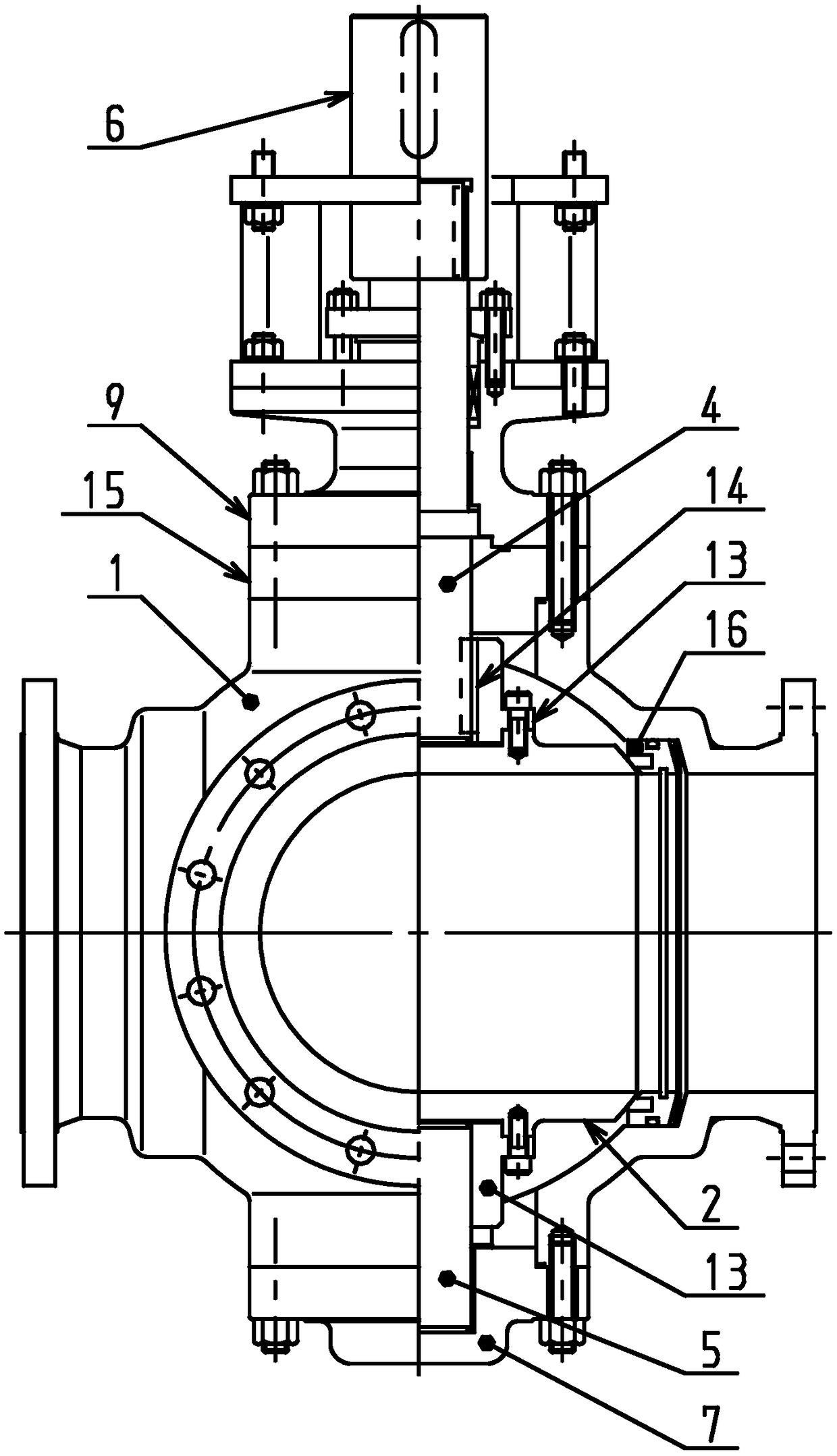
[0027] Such as figure 1 and figure 2 As shown, this embodiment provides a three-way ball valve, which includes a valve body 1, a ball 2, a fixing member 3, an upper valve stem 4, a lower valve stem 5, a coupling 6, and a driving device (not shown in the figure) And the lower valve cover 7, the support plate 15 is located on the upper side of the valve body 1, and the lower valve cover 7 covers the lower opening of the valve body 1. It should be noted, figure 1 and figure 2 The left side is the main view, and the right side is the section view.
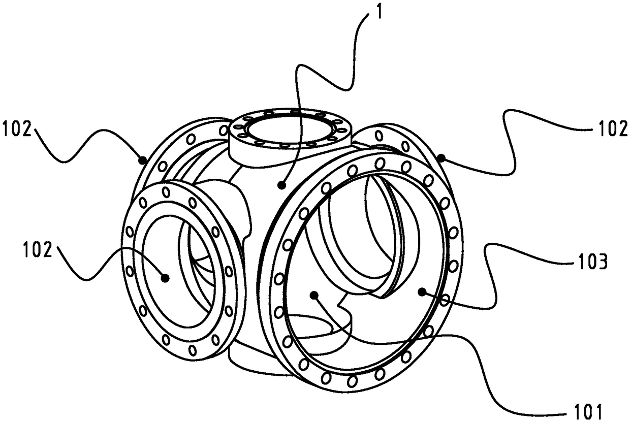
[0028] Such as image 3 As shown, the interior of the valve body 1 is hollow to form a cavity channel 101 , and a mounting hole 103 and three first openings 102 are provided on the side wall of the valve body 1 , and both the mounting hole 103 and the first openings 102 communicate with the cavity channel 101 .
[0029] In this embodiment, the inner hollow ball 2 is arranged in the cavity channel 101 of the three-way ball valve....
Embodiment 2
[0038] This embodiment provides another three-way ball valve, which is basically the same as Embodiment 1, and only the different parts will be introduced below.
[0039] Such as figure 1 As shown, in this embodiment, the three-way ball valve also includes an upper bonnet 9, the upper bonnet 9 is located on the upper side of the support plate 15, and is fixed to the upper side of the valve body 1 through the support plate 15, and the upper valve stem 4 passes through Over the upper valve cover 9, and connected with the upper valve cover 9 in rotation. The upper valve cover 9 can better protect the valve body 1 .
[0040] Preferably, as figure 2 As shown, the three-way ball valve also includes a shaft sleeve 10 and a thrust pad 11, through which the upper valve stem 4 is rotationally connected with the upper valve cover 9, the inner side of the shaft sleeve 10 fits the upper valve stem 4, and the thrust pad 11 is placed on Above the shaft shoulder of the upper valve stem 4 ...
Embodiment 3
[0043] This embodiment provides another three-way ball valve, which is basically the same as Embodiment 1, and only the different parts will be introduced below.
[0044] Such as figure 1 and Figure 5 As shown, in this embodiment, the three-way ball valve also includes two connectors 13, and the two connectors 13 are respectively fixed on the upper surface 202 and the lower surface 203 of the ball 2, and the upper valve stem 4 passes through the upper surface of the ball 2. The connector 13 is keyed to the sphere 2 , and the lower valve stem 5 is rotatably connected to the sphere through the connector 13 located on the lower surface of the sphere 2 . Wherein, the upper valve stem 4 is keyed to the sphere 2 through the connector 13, and the lower valve stem 5 is rotatably connected to the sphere 2 through the connector 13, which simplifies the connection structure between the upper valve stem 4 and the lower valve stem 5 and the sphere 2.
[0045] Preferably, the three-way b...
PUM
 Abstract
Description
Claims
Application Information
 - R&D
- Intellectual Property
- Life Sciences
- Materials
- Tech Scout
- Unparalleled Data Quality
- Higher Quality Content
- 60% Fewer Hallucinations
Browse by: Latest US Patents, China's latest patents, Technical Efficacy Thesaurus, Application Domain, Technology Topic, Popular Technical Reports.
© 2025 PatSnap. All rights reserved.Legal|Privacy policy|Modern Slavery Act Transparency Statement|Sitemap|About US| Contact US: help@patsnap.com