Nozzle for laser processing head

Active Publication Date: 2018-07-19
FANUC LTD
View PDF16 Cites 4 Cited by
  • Summary
  • Abstract
  • Description
  • Claims
  • Application Information

AI Technical Summary

Benefits of technology

The present invention relates to a nozzle for laser processing which can reliably drill a small hole in a workpiece and reduce drilling time, even if the workpiece is thick. The nozzle can also prevent the optical system from being contaminated by melted material. The technical effect of the invention is to achieve faster and more reliable laser drilling with improved enclosure of the nozzle tip body and reduced adhesiveness of melted material.

Problems solved by technology

However, this is inconvenient as follows.
First, there is a risk that, when a small hole is opened, due to influence of the assist gas, not only the laser received area of the workpiece but also a peripheral region thereof is deformed or removed by thermal conduction from the melted material, and the hole diameter becomes larger than that is intended.
Second, when the workpiece is thick or high in specific gravity (hereinafter, referred to as “when the workpieces is thick, or the like”), in a process of drilling by laser processing, the melted material becomes difficult to be removed and drilling takes much time.
Third, in drilling of the workpiece, the laser received area of the workpiece is heated suddenly, and the temperature of the workpiece exceeds instantaneously the melting point and the boiling point.
Thus, the melted material splashes to a laser irradiating direction and contaminates an optical system such as a lens and a window.

Method used


Image

  • Nozzle for laser processing head
  • Nozzle for laser processing head
  • Nozzle for laser processing head

Examples


first embodiment

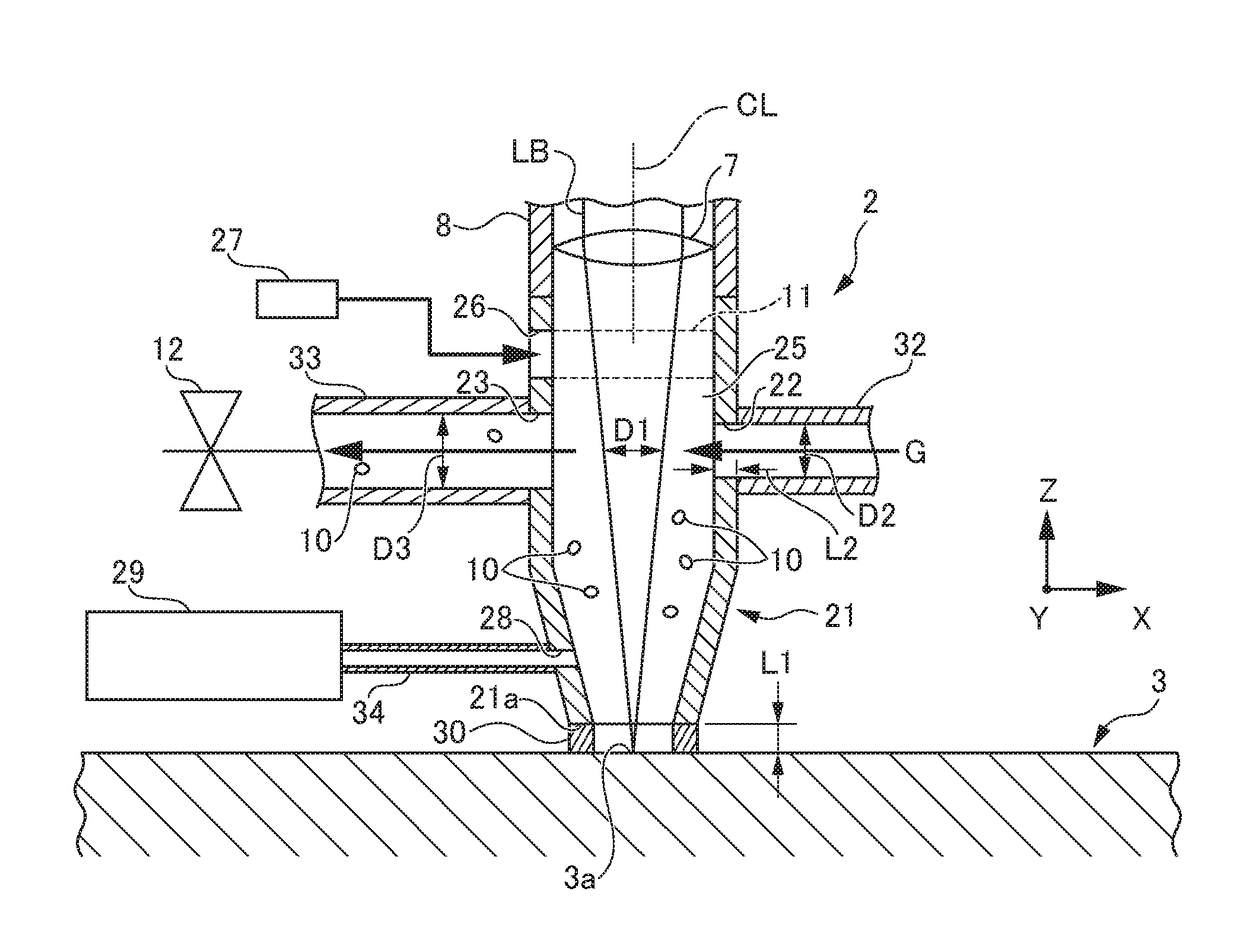
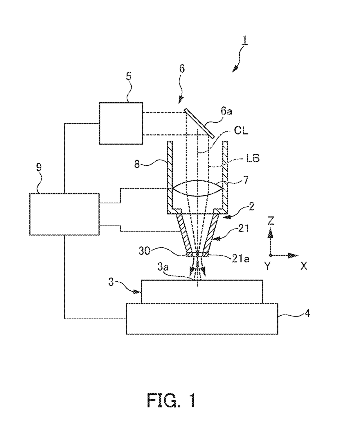
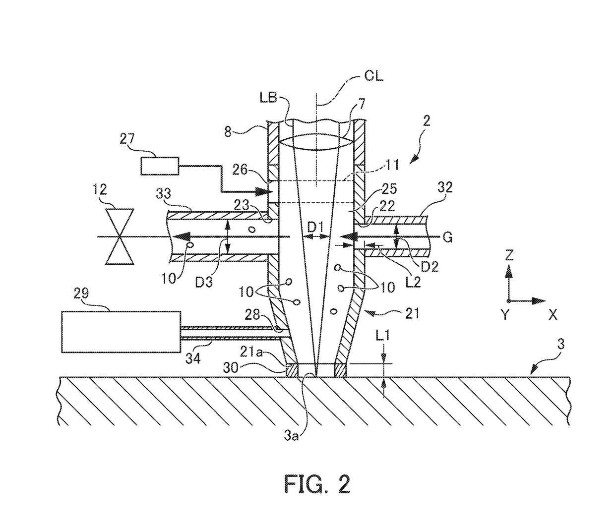
[0022]FIG. 1 is a schematic configuration diagram showing a laser machine according to a first embodiment. FIG. 2 is a vertical cross section view showing a nozzle of the laser machine according to the first embodiment.

[0023]As shown in FIG. 1, a laser machine 1 according to the first embodiment includes: a movable table 4 that horizontally supports a flat plate-shaped workpiece 3 of aluminum; a laser oscillator 5 that emits a laser beam LB having a circular cross section; a light guide path 6 that guides the laser beam LB emitted from the laser oscillator 5 to the workpiece 3; a processing head 8 that focuses the laser beam LB by a focusing lens 7 and irradiates the workpiece 3 with the laser beam LB; a nozzle 2 mounted to a tip end of the processing head 8; and a controller 9 that controls operation of the movable table 4, the laser oscillator 5, and the processing head 8.

[0024]The movable table 4 is movable to an X axis direction and a Y axis direction. The processing head 8 is m...

second embodiment

[0046]FIG. 3 is a vertical cross section view showing the nozzle of a laser machine according to a second embodiment. FIG. 4 is a horizontal cross section view showing the nozzle of the laser machine according to the second embodiment.

[0047]The laser machine 1 according to the second embodiment has a different configuration of the nozzle 2 from that of the first embodiment described above, as follows. Other configurations are basically similar to those of the first embodiment described above. Thus, the same members are added with the same numerals, and description thereof is omitted.

[0048]As shown in FIG. 3 and FIG. 4, in the nozzle 2 of this laser machine 1, an airflow generator 15 that generates a helical rising airflow in the inside of the nozzle tip body 21 is attached to the nozzle tip body 21. This airflow generator 15 is composed of a first gas path 15a that supplies gas from the outside of the nozzle tip body 21, via the inside of the nozzle tip body 21, to the outside, and ...


PUM

PropertyMeasurementUnit
Pressureaaaaaaaaaa
Diameteraaaaaaaaaa
Adhesivityaaaaaaaaaa

Abstract

To provide a nozzle for laser processing head capable of reliably drilling a small hole when drilling of the workpiece is performed by using a laser machine. A nozzle includes: a nozzle tip body that irradiates a workpiece with a laser beam; a charge port formed in the nozzle tip body; an exhaust port formed in the nozzle tip body so as to oppose to the charge port; and an elastic member that is provided in a tip end of the nozzle tip body and contacts with the workpiece while elastically extending and contracting in the axial center direction of the nozzle tip body. The nozzle supplies gas to the inside of the nozzle tip body along a gas flow path extending from the charge port to the exhaust port in a form of crossing across the laser beam in the nozzle tip body, to generate a negative pressure in the vicinity of an opening part of a tip end of the nozzle tip body. The elastic member contacts with the workpiece and improves the degree of enclosure of the nozzle tip body by the workpiece. Thereby, higher negative pressure than the negative pressure is generated.

Description

[0001]This application is based on and claims the benefit of priority from Japanese Patent Application No. 2017-007919, filed on 19 Jan. 2017, the content of which is incorporated herein by reference.BACKGROUND OF THE INVENTIONField of the Invention[0002]The present invention relates to a nozzle mounted to a tip end of a processing head of a laser machine, that is, a nozzle for laser processing head.Related Art[0003]Conventionally, when drilling is performed by using a laser machine, in order to blow away and remove a melted material generated in a laser light received area of a workpiece, and accelerate combustion of the workpiece, assist gas such as nitrogen and oxygen is blown to the laser light received area of the workpiece coaxially with a laser beam (refer to Patent Document 1 as an example).[0004]Patent Document 1: Japanese Unexamined Patent Application, Publication No. 2013-27907SUMMARY OF THE INVENTION[0005]However, this is inconvenient as follows.[0006]First, there is a r...

Claims


Application Information

Patent Timeline
IPC IPC(8): B23K26/142B23K26/14B23K26/382
CPCB23K26/142B23K26/1436B23K26/147B23K26/382
Inventor IZUMI, TAKASHI
Owner FANUC LTD
Why Eureka
Try Eureka