Machine learning apparatus and coil electric heating apparatus

Active Publication Date: 2017-03-30
FANUC LTD
View PDF4 Cites 1 Cited by
  • Summary
  • Abstract
  • Description
  • Claims
  • Application Information

AI Technical Summary

Benefits of technology

The present invention is about a machine learning system that can optimally heat coils without needing detailed information about how to use them. This system is designed for use in a coil electric heating apparatus. The technical effect of this invention is to improve the efficiency and accuracy of heating coils.

Problems solved by technology

However, when the degree of heating of the winding wire 2, which has been electrically heated, is insufficient, the adhesiveness of the hot-melt adhesive 3 decreases, and thus, the unit coil is uncoiled.
Further, a lot of labor and man-hour are required because it is necessary for an operator to manually set operation conditions through trial and error.

Method used


Image

  • Machine learning apparatus and coil electric heating apparatus
  • Machine learning apparatus and coil electric heating apparatus
  • Machine learning apparatus and coil electric heating apparatus

Examples


Embodiment Construction

[0025]Embodiments of the present invention will be described below with reference to the accompanying drawings. In the following figures, similar members are designated with the same reference numerals. These figures are properly modified in scale to assist the understanding thereof.

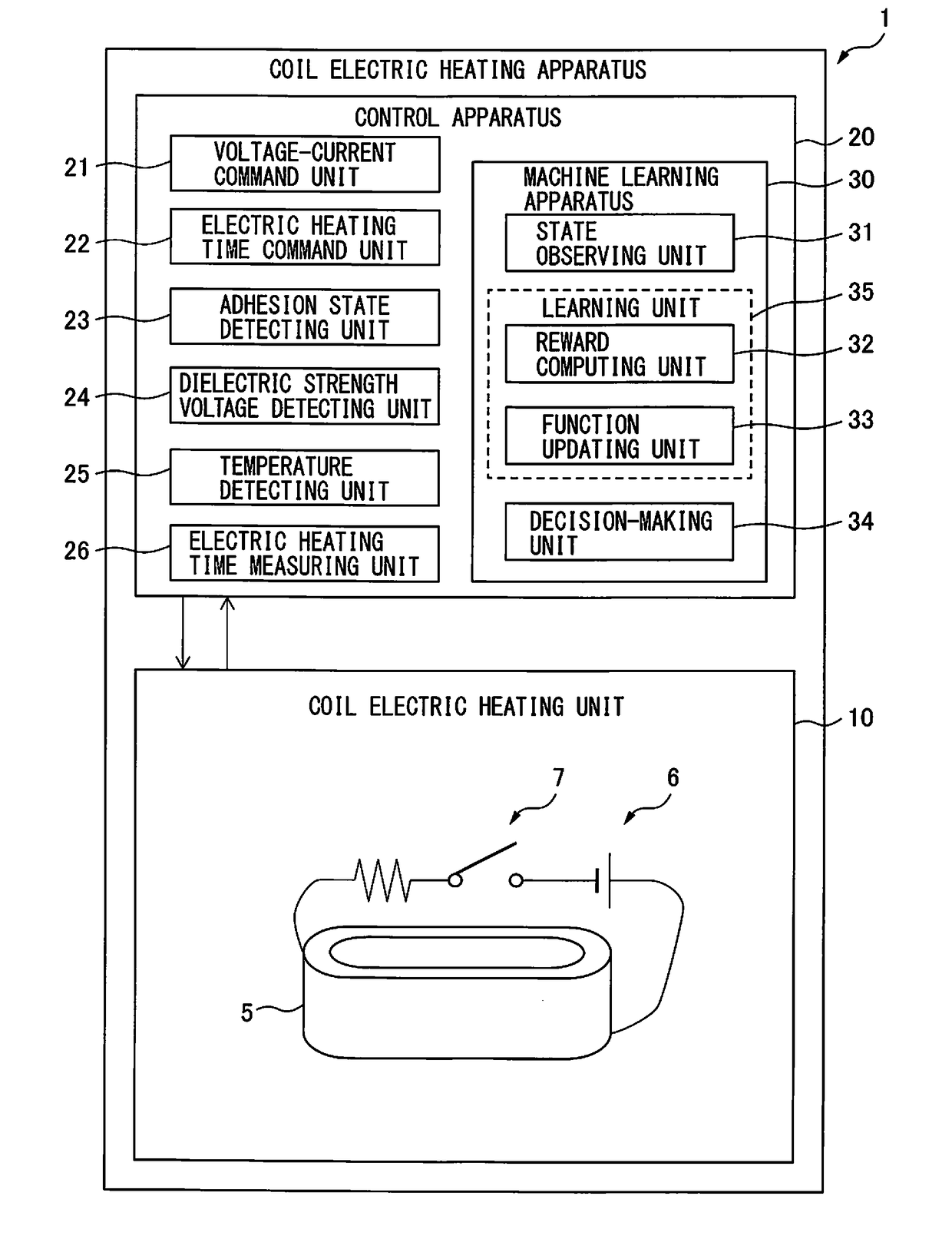
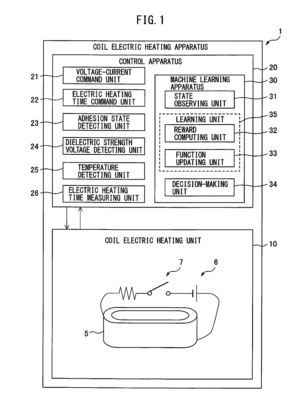
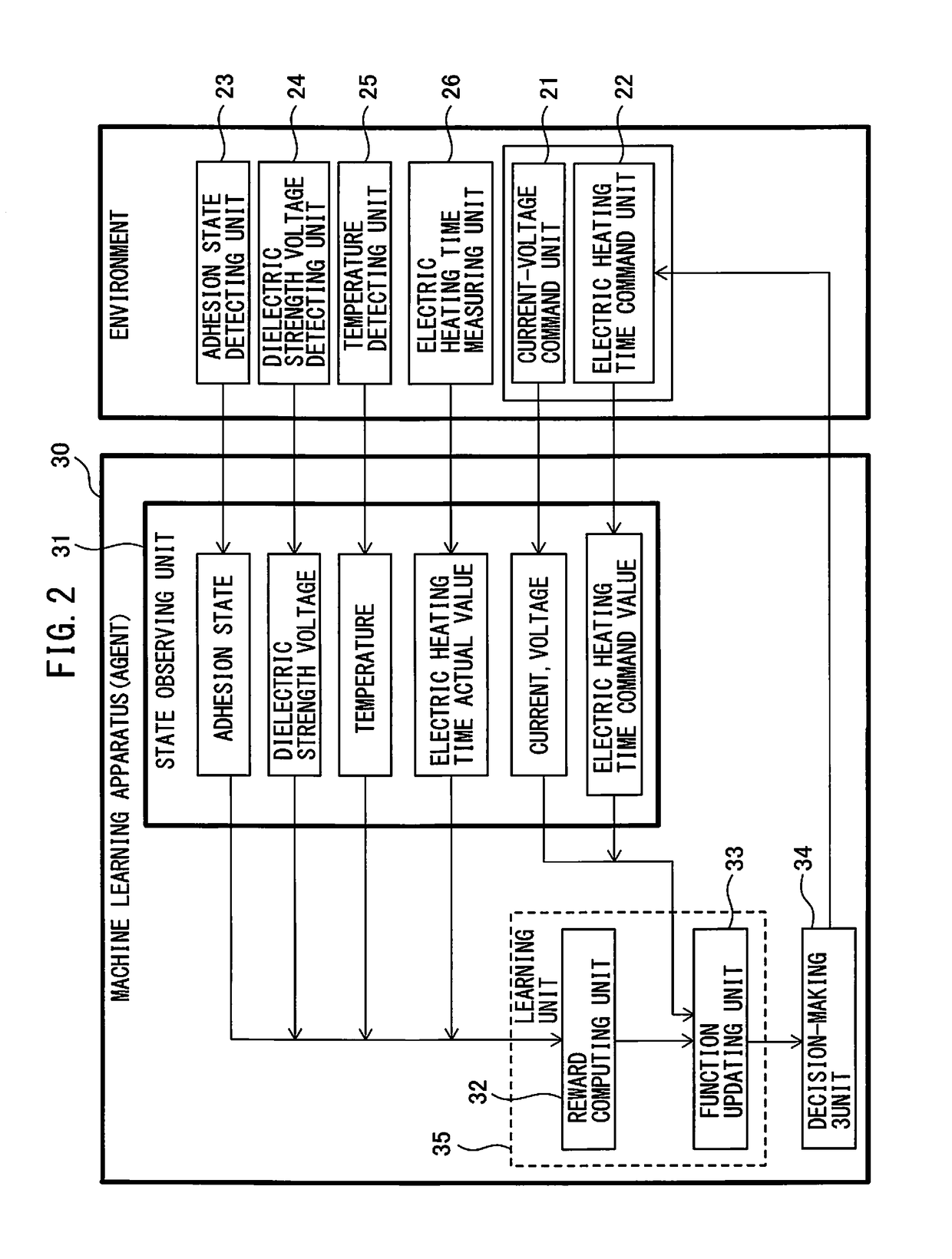
[0026]FIG. 1 is a block diagram of the functions of a coil electric heating apparatus according to the present invention. As shown in FIG. 1, a coil electric heating apparatus 1 mainly includes a coil electric heating unit 10 and a control apparatus 20 for controlling the coil electric heating unit 10.

[0027]FIG. 1 shows, in its lower part, the coil electric heating unit 10. The coil electric heating unit 10 energizes a coil 5 which is wound by a winding machine which is not illustrated. Specifically, as shown in FIG. 1, a power source 6 is connected to the starting end and the terminal end of winding of the coil 5, to energize the coil 5. Note that, as described above, a wire rod 2 of the coil 5 is coate...


PUM


Abstract

A machine learning apparatus includes a state observing unit and a learning unit. The state observing unit observes a state variable comprised of at least one of an adhesion state, a dielectric strength voltage, an electric heating time temperature, and an actual electric heating time value of a coil electrically heated by a coil electric heating unit, and at least one of an electric heating time command value, a voltage, and a current in the coil electric heating unit. The learning unit performs a learning operation by linking at least one of an adhesion state, a dielectric strength voltage, an electric heating time temperature, and an actual electric heating time value of the coil observed by the state observing unit to at least one of the electric heating time command value, the voltage, and the current, which are observed by the state observing unit.

Description

BACKGROUND OF THE INVENTION[0001]1. Field of the Invention[0002]The present invention relates to a machine learning apparatus and a coil electric heating apparatus including such a machine learning apparatus.[0003]2. Description of the Related Art[0004]A unit coil 50 (hereinafter simply referred to as “coil” in some cases) formed by a winding machine is fitted with a tooth part of a stator 60 as shown in FIG. 5A. Further, as shown in FIG. 5B, a plurality of unit coils 50 is arranged so as to be fitted with a plurality of tooth parts of the stator 50.[0005]FIGS. 6A and 6B are partial sectional enlarged views of a unit coil. As shown in FIG. 6A, in order to fix the shape of a unit coil, hot-melt adhesive 3 is previously applied to a winding wire 2 (see Japanese Unexamined Patent Publication (Kokai) Nos. 2005-71644, 2002-231552, 7-50218, and 2002-358836). After the unit coil is wound, the winding wire 2 is energized to be heated (electrically heated). Consequently, as shown in FIG. 6B,...

Claims


Application Information

Patent Timeline
IPC IPC(8): H05B1/02G06N99/00
CPCG06N99/005H05B1/0288H01F41/04H02K15/0442G06N20/20G06N5/01G06N7/01G06N20/00
Inventor SUGIMOTO, YASUNORI
Owner FANUC LTD
Why Eureka
Try Eureka