Switching power supply device

a power supply device and switching power supply technology, applied in the direction of electric variable regulation, process and machine control, instruments, etc., can solve the problems of difficult to make the switching power supply device more compact and lightweight, and the cost of the switching power supply device becomes greater, so as to achieve the effect of less cost, less weight, and compact siz

Active Publication Date: 2018-07-12
FUJI ELECTRIC CO LTD
View PDF7 Cites 3 Cited by
  • Summary
  • Abstract
  • Description
  • Claims
  • Application Information

AI Technical Summary

Benefits of technology

The present invention aims to provide a switching power supply device that eliminates the need for external components for overvoltage protection control. This is achieved by conferring an overvoltage protection function to the control unit for controlling switching devices. This results in a device that is lower in cost, more compact in size, and lighter in weight as there is no need for external components.

Problems solved by technology

However, overvoltage protection control requires an overvoltage detection circuit and a photocoupler as external components, and thus not only does the cost of the switching power supply device become greater, but it becomes difficult to make the switching power supply device more compact and lightweight.

Method used


Image

  • Switching power supply device
  • Switching power supply device
  • Switching power supply device

Examples


embodiment 1

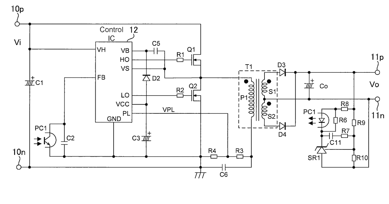
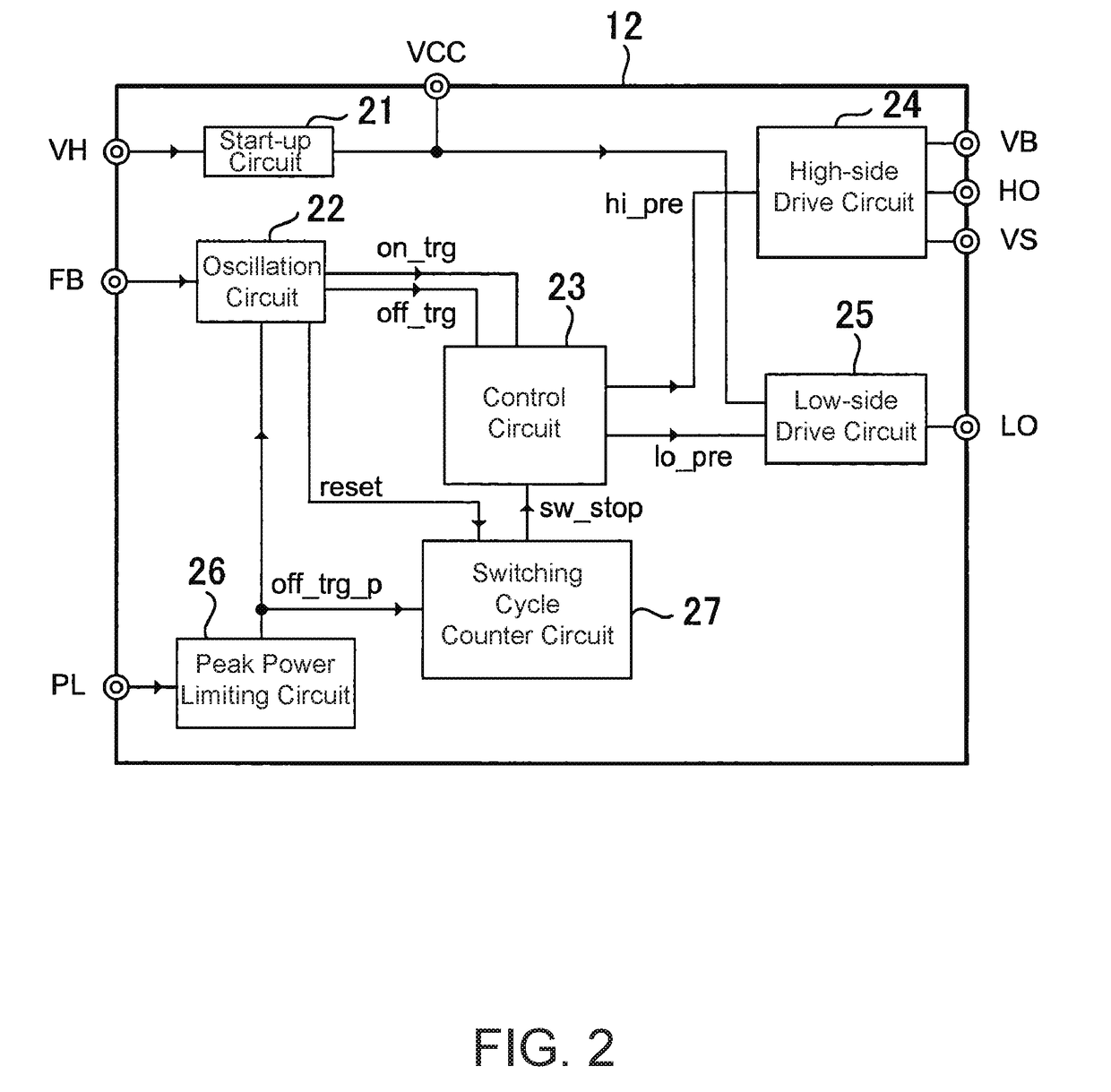
[0026]FIG. 1 is a circuit diagram showing a configuration example of a switching power supply device provided with a current resonant DC-DC converter according to Embodiment 1, FIG. 2 is a diagram showing a configuration example of a control IC, and FIG. 3 is a drawing showing an operation sequence of the current resonant switching power supply device.

[0027]The switching power supply device of Embodiment 1 has two input terminals 10p and 10n to which an input capacitor C1 is connected, and receives a direct-current input voltage Vi that has been made uniform via a high voltage generated by a power factor improvement circuit, for example. The input terminals 10p and 10n have connected thereto a series circuit of a high-side switching device Q1 and low-side switching device Q2 and form a half-bridge circuit. In the example shown in the drawings, N-channel MOSFETs (metal oxide semiconductor field effect transmitters) are used as the switching devices Q1 and Q2.

[0028]The node shared by ...

embodiment 2

[0058]FIG. 9 is a circuit diagram showing a configuration example of a switching power supply device provided with a current resonant DC-DC converter according to Embodiment 2, FIG. 10 is a circuit diagram showing a configuration example of a peak power limiting circuit, and FIG. 11 is a drawing showing an operation sequence of the peak power limiting circuit during peak power limiting. In FIG. 9, constituent elements that are the same or similar to those shown in FIG. 1 are given the same reference characters and detailed explanations thereof are omitted.

[0059]As shown in FIG. 9, in the switching power supply device provided with the current resonant DC-DC converter according to Embodiment 2, a transformer T1a has an auxiliary coil P2 on a primary side thereof. One terminal of the auxiliary coil P2 is connected to one terminal of a resistor R3, and the other terminal of the auxiliary coil P2 is connected to ground. The other terminal of the resistor R3 is connected to one terminal ...


PUM


Abstract

A switching power supply device includes a control unit alternately turning a first switching device and a second switching device ON / OFF so as to drive a primary side of a transformer, wherein the control unit includes: a peak power limiting circuit that monitors input power to the primary side of the transformer and outputs a forced turn OFF signal every time the input power becomes higher than a prescribed value; and a switching cycle counter circuit that estimates an output voltage on a secondary side of the transformer by counting a number of times the forced turn OFF signal is outputted by the peak power limiting circuit, and outputs a switching stop signal that causes the alternating turning ON / OFF of the first and second switching devices to stop when the estimated output voltage reaches an overvoltage protection detection voltage.

Description

BACKGROUND OF THE INVENTIONTechnical Field[0001]The present invention relates to a switching power supply device, and particularly relates to a switching power supply device that is a current resonant DC-DC converter.Background Art[0002]Current resonant DC-DC converter switching power supply devices can be made highly efficient and thin, and are therefore widely employed in liquid-crystal televisions, AC-DC adapters, and so on. A current resonant DC-DC converter switching power supply device generally includes a half-bridge circuit in which two switching devices are connected in series, a resonant capacitor, a transformer, an output rectifying diode, and an output capacitor. The transformer used in the switching power supply device is often used as a resonant inductor by increasing the leakage inductance component through decreasing the coupling coefficient.[0003]The switching devices constituting the half-bridge circuit are connected to a control unit and are alternately turned ON / ...

Claims


Application Information

Patent Timeline
Patent Type & Authority Applications(United States)
IPC IPC(8): H02M1/32H02M3/335H02M1/08
CPCH02M1/32H02M3/33569H02M1/08H02M3/3376Y02B70/10H02M1/0058H02M3/33571H02M3/01
Inventor CHEN, JIAN
Owner FUJI ELECTRIC CO LTD
Why Eureka
Try Eureka