
Mixed-reality architectural design environment

a mixed-reality architecture and design environment technology, applied in the field of mixed-reality architectural design environment, can solve the problems of inability to accurately portray the scale of finished products, cumbersome navigation and many shortcomings of conventional three-dimensional renderings

Active Publication Date: 2018-07-12
ARMSTRONG WORLD INDUSTRIES
View PDF4 Cites 39 Cited by
  • Summary
  • Abstract
  • Description
  • Claims
  • Application Information

AI Technical Summary

Benefits of technology

The present invention is a system, method, and apparatus for creating a mixed-reality environment where users can navigate and interact with a three-dimensional rendering of an architectural design. The system includes a computer system for managing multiple distinct perspectives within a mixed-reality design environment, which loads a three-dimensional architectural model into memory and associates it with a virtual coordinate system. The computer system then transmits rendering information to devices with independent variable functions that map the virtual coordinate system to a physical coordinate system within a real-world environment. The invention allows users to experience the architectural design from unique perspectives and provides a more immersive user experience.

Problems solved by technology

While three-dimensional renderings can provide a user with a general idea regarding a final product, conventional three-dimensional renderings suffer from several shortcomings.
For example, navigation of conventional three-dimensional renderings can be cumbersome as a user tries to achieve particular views of various features.
Additionally, conventional systems may not be able to portray a true scale of a finished product.
Accordingly, there are a number of problems in the art that can be addressed.

Method used


Image

  • Mixed-reality architectural design environment
  • Mixed-reality architectural design environment
  • Mixed-reality architectural design environment

Examples


Embodiment Construction

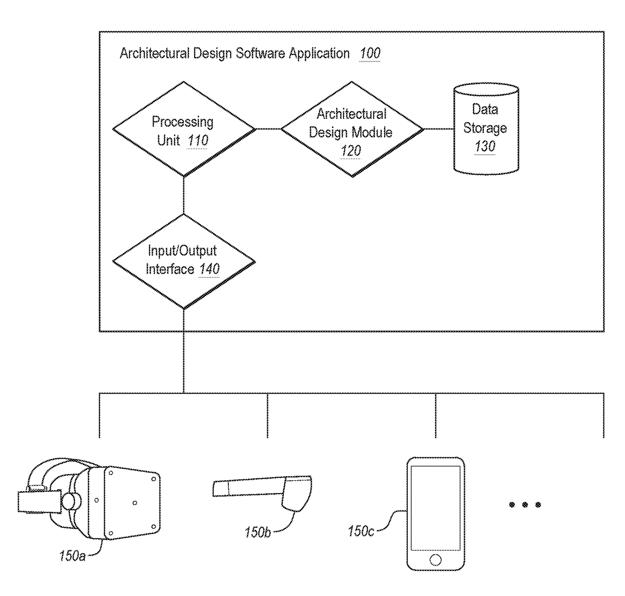
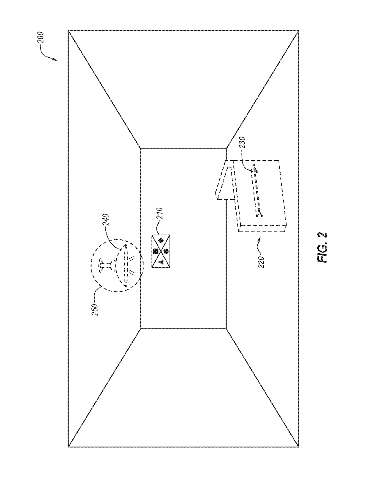
[0019]Disclosed embodiments extend to systems, methods, and apparatus configured to allow one or more users to navigate and interact with a three-dimensional rendering of an architectural design. In particular, implementations of the present invention comprise mixed-reality components that create a mixed-reality environment that immerses a user. For example, the mixed-reality components may comprise a headset that at least partially covers a user's eyes and tracks the viewing angle of the user's eyes and / or head movement, a mobile phone that displays, to a user, mixed-reality elements, or any other device capable of providing a user a view of a real-world environment and accompanying mixed-reality elements. As such, the mixed-reality components can be used to generate a mixed-reality environment that allows a user to interact with an architectural design within a real-world space.

[0020]Disclosed embodiments include a mixed-reality architectural design system that injects mixed-reali...


PUM


Abstract

A computer system for managing multiple distinct perspectives within a mixed-reality design environment loads a three-dimensional architectural model into memory. The three-dimensional architectural model is associated with a virtual coordinate system. The three-dimensional architectural model comprises at least one virtual object that is associated with an independently executable software object that comprises independent variables and functions that are specific to a particular architectural element that is represented by the at least one virtual object. The computer system associates the virtual coordinate system with a physical coordinate system within a real-world environment. The computer system transmits to each device of multiple different devices rendering information. The rendering information comprises three-dimensional image data for rendering the three-dimensional architectural model and coordinate information that maps the virtual coordinate system to the physical coordinate system.

Description

BACKGROUND[0001]As computerized systems have increased in popularity, so have the range of applications that incorporate computational technology. Computational technology now extends across a broad range of applications, including a wide range of productivity and entertainment software. Indeed, computational technology and related software can now be found in a wide range of generic applications that are suited for many environments, as well as fairly industry-specific software.[0002]One such industry that has employed specific types of software and other computational technology increasingly over the past few years is that related to building and / or architectural design. In particular, architects and interior designers (“or designers”) use a wide range of computer-aided design (CAD) software or building information (BIM) software (i.e., “architectural design software applications”) for designing the aesthetic as well as functional aspects of a given residential or commercial space...

Claims


Application Information

Patent Timeline
IPC IPC(8): G06T19/00G06T15/10G06T15/04
CPCG06T19/006G06T15/10G06T15/04G06T2210/04G06F3/04842G06F3/017
Inventor LOBERG, BARRIE A.HOWELL, JOSEPHBLODGETT, ROBERTSTANNUS, SIMON FRANCISHIBBERD, MATTHEWWEST, TYLER
Owner ARMSTRONG WORLD INDUSTRIES
Learn More