Converter valve fault warning method and system

a converter valve and fault warning technology, applied in the field of high-power electronics, can solve the problems of performance degradation, shortened service life of some thyristor levels, and slight differences in voltage-balancing consistency of thyristor levels, so as to improve the safe and reliable operation of the direct current system, reduce the probability of outage, and reduce the risk of direct current system outage

Active Publication Date: 2018-07-12
NR ELECTRIC CO LTD +1
View PDF7 Cites 1 Cited by
  • Summary
  • Abstract
  • Description
  • Claims
  • Application Information

AI Technical Summary

Benefits of technology

The method and system described in this patent can identify which thyristor level is more likely to fail and provide an early warning, reducing the likelihood of outage of a direct current system due to a failure of a thyristor level. Additionally, the method and system can provide a reference for device replacement, improving the safety and reliability of the direct current system. It can also help in optimizing device performance and circuit design of the converter valve. The method and system use statistical analysis and selection of status indication signals from the converter valve to achieve bias analysis on performance differences between thyristor levels and predict which thyristor level is likely to fail.

Problems solved by technology

After a long time of operation, a failure may occur due to performance degradation.
In addition, there are slight differences in voltage-balancing consistency of the thyristor levels due to slight differences in parameters of the resistance-capacitance circuits.
Under a long-time high-voltage operation condition, the service life of some thyristor levels may be shortened, and in a severe case, the risk of outage of the direct current system is caused by failures of several thyristor levels, which adversely affects safe and stable operation of the direct current system.

Method used


Image

  • Converter valve fault warning method and system
  • Converter valve fault warning method and system
  • Converter valve fault warning method and system

Examples


Embodiment Construction

[0035]The technical solution of the present invention is described in detail below with reference to the accompanying drawings.

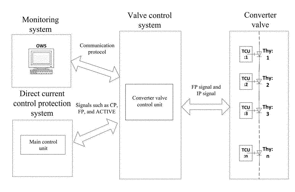
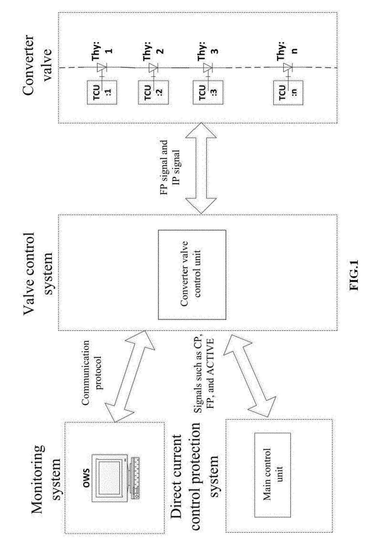
[0036]The present invention provides an early warning system for a failure in a converter valve. The system is implemented based on a converter VCU. The converter VCU is a critical core device of an entire converter valve control system. A schematic structural diagram of the converter valve control system is provided in FIG. 1. The converter valve control system implements the control of a converter valve under various operating conditions. The converter valve control system consists essentially of a direct current control protection system, a converter VCU, and a TCU. The converter VCU serves as a bridge between the direct current control protection system and the converter valve, and mainly functions to receive control signals sent by the direct current control protection system, and generate a trigger pulse according to the control signals and using a log...


PUM


Abstract

Within a predetermined time range, record time information of status indication signals fed back by thyristor control units (TCU) of a converter valve. Perform, statistics and comparison of the pieces of time information using a bias statistics method. Mark, a thyristor level whose bias exceeds a preset value. And determine a probability of failure in the thyristor according to the marking result.

Description

BACKGROUND OF THE INVENTION1. Field of the Invention[0001]The present invention relates to the field of high-power electronics, and more particularly to an early warning method and system for a failure in a converter valve.2. Description of the Prior Art[0002]High-voltage direct current (HVDC) power transmission is the most important, most traditional, and most rapidly developing one among applications of power electronics technology. The working performance of a converter valve, as a primary core device in HVDC power transmission projects, directly determines the operation stability of direct current power transmission. A converter valve control system is used to implement the control of the converter valve under various operating conditions. The converter valve control system consists essentially of a direct current control protection system, a converter valve control unit (VCU), and a thyristor control unit (TCU). The converter VCU serves as a bridge between the direct current co...

Claims


Application Information

Patent Timeline
IPC IPC(8): G01R31/08H02J13/00
CPCG01R31/08H02J13/00H02J13/0062G01R31/088H02J13/00001H02M1/088H02M1/32H02M7/7575Y02E60/60G01R31/40G08B21/185Y04S10/20Y02E60/00
Inventor GAO, SHENGFUFANG, TAIXUNWANG, YONGPINGZHANG, XIANGPAN, WEIMINGYUAN, MINGZHOU, GUQING
Owner NR ELECTRIC CO LTD
Why Eureka
Try Eureka