Calibration device, calibration method, and computer readable medium for visual sensor

a technology of visual sensor and calibration method, applied in image analysis, image enhancement, program-controlled manipulators, etc., can solve the problems of consuming unnecessary time to reduce efficiency, affecting the operability of an operator, and distorted shape of a target mark appearing in the camera

Active Publication Date: 2018-07-12
FANUC LTD
View PDF0 Cites 17 Cited by
  • Summary
  • Abstract
  • Description
  • Claims
  • Application Information

AI Technical Summary

Benefits of technology

[0023]A calibration device, a calibration method, and a program provided by the present invention are capable of eliminating the need to generate a mode

Problems solved by technology

However, the multiple cameras are attached at separate positions, so that the shapes of a target mark appearing in the cameras are distorted in different ways.
However, generating a model pattern and se

Method used


Image

  • Calibration device, calibration method, and computer readable medium for visual sensor
  • Calibration device, calibration method, and computer readable medium for visual sensor
  • Calibration device, calibration method, and computer readable medium for visual sensor

Examples


Embodiment Construction

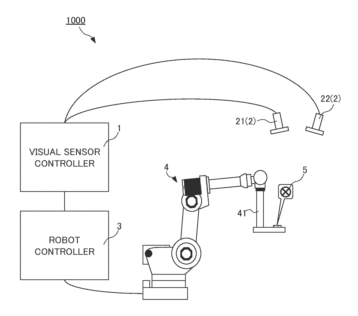
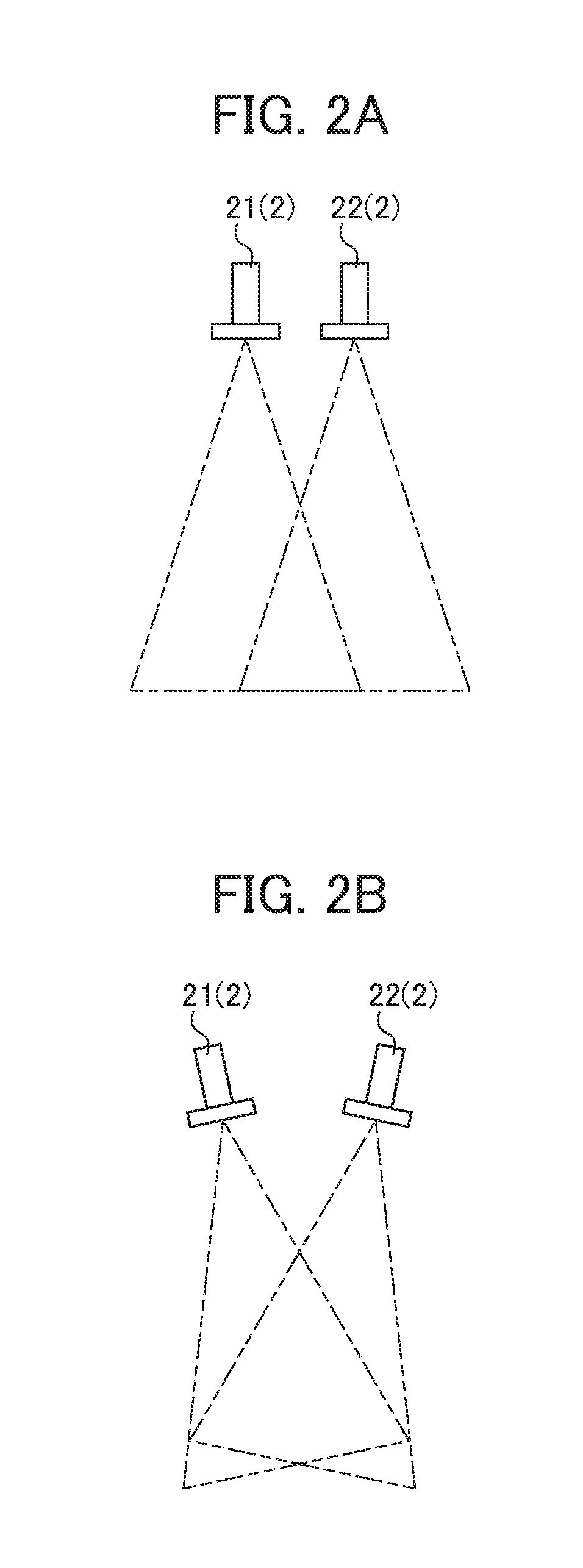
[0039]An example of an embodiment of the present invention will be described below. In this embodiment, a visual sensor controller is described as an example of a calibration device. FIG. 1 shows the configuration of a robot system 1000 entire for performing calibration on a visual sensor, particularly calibration by using a stereo camera with multiple cameras. As shown in FIG. 1, the robot system 1000 includes: the stereo camera 2 with two cameras (a first camera 21 and a second camera 22); a visual sensor controller 1 (as a calibration device) that makes three-dimensional measurement through image processing on data about an image captured by the stereo camera 2; a robot 4 having an arm 41 with an end portion to which a target mark 5 is attached; and a robot controller 3 for control over the robot 4. The number of cameras forming the stereo camera 2 is not limited to two but can be any number of two or more. Each of the cameras forming the stereo camera 2 is certainly applicable a...


PUM


Abstract

A parameter for detecting a target mark 5 is not required to be set for each camera repeatedly while a stereo camera 2 is calibrated. A calibration device 1 associates position information in an image coordinate system at a first camera 21 of a stereo camera 2, position information in an image coordinate system at a second camera 22 of the stereo camera 2, and position information in a robot coordinate system at a robot 4. The calibration device comprises: first parameter setting unit 102 that sets a first parameter for detecting a target mark 5 attached to the robot 4 from data about an image captured by the first camera 21; and a second parameter setting unit 104 that sets a second parameter for detecting the target mark 5 from data about an image captured by the second camera 22 based on the first parameter.

Description

[0001]This application is based on and claims the benefit of priority from Japanese Patent Application No. 2017-00664, filed on 12 Jan. 2017, the content of which is incorporated herein by reference.BACKGROUND OF THE INVENTIONField of the Invention[0002]The present invention relates to calibration on a visual sensor, particularly, to a calibration device, a calibration method, and computer readable medium encoded with a program for detecting a target mark during implementation of calibration using a stereo camera with multiple cameras.Related Art[0003]In a robot system, a robot is given a visual function. Operation such as handling or machining on a work is done by making the robot recognize the position of a subject. This visual function is fulfilled by capturing an image of the subject with a visual sensor attached to a hand or a neighboring part of the robot or a visual sensor provided around the robot. In such a robot system, to acquire the position information of the subject vi...

Claims


Application Information

Patent Timeline
IPC IPC(8): B25J9/16G06T7/80B25J19/04
CPCB25J9/1692G06T7/85B25J9/1697B25J19/04B25J9/163B25J9/1653B25J9/1671B25J19/023G06T2207/10012G06T2207/30204
Inventor NAMIKI, YUUTAWARASHINA, FUMIKAZU
Owner FANUC LTD
Why Eureka
Try Eureka