
Mass spectrometer and method applied thereby for reducing ion loss and succeeding stage vacuum load

a mass spectrometer and vacuum load technology, applied in the field of mass spectrometry, can solve the problems of difficult to achieve high efficiency, low sampling efficiency, and limited focusing effect of radio-frequency voltage, so as to improve the efficiency of ion capture and improve the desolvation efficiency of charged droplets, the effect of improving the sensitivity of the mass spectrometer

Active Publication Date: 2018-06-21
SHIMADZU CORP
View PDF0 Cites 1 Cited by
  • Summary
  • Abstract
  • Description
  • Claims
  • Application Information

AI Technical Summary

Benefits of technology

The present invention aims to improve vacuum interfaces in a mass spectrometer to reduce ion loss and increase the efficiency of the analyte transfer process. This will be achieved without adding a subsequent vacuum load that may affect the overall performance of the mass spectrometer.

Problems solved by technology

Therefore, if only a radio-frequency multipole or other optical devices is used for transferring or focusing the ions after the ions have passed through the Mach disc, and it is hard to achieve a high efficiency due to a high ion-scattering speed.
Based on the conventional solution to this problem, another sampling cone hole is used for capturing part of the ions before ion-scattering occurs, methods such as the radio-frequency multipole and the like may be used for focusing the ions transferred as no dramatic and sudden gas pressure change occurs, but the sampling efficiency is very low by adopting said method.
However, this method also has the problems that no adjustment is made to the gas flow itself on the one hand, and the focusing effect of the radio-frequency voltage is very limited under the effect of high speed gas flow, so that it is hard to ensure no ion loss.
For a non-scanning type mass analyzer such as a time of flight mass spectrum, such a method limits the efficiency of analysis.
Obviously, such a long rectifier tube is undesirable for the miniaturization of the instrument, and the ion loss caused by a long-distance transfer will increase greatly.
In such a strong flow field, it is difficult to effectively focus the ions by application of an electric field, and the high-speed gas flow will rush into a succeeding stage vacuum, adding to the burden placed upon the vacuum pump.
However, introduction of the off-axis configuration significantly adds the design complexity of the interface and easily causes a phenomenon of mass discrimination due to the difference in ion mobility of different ions.

Method used


Image

  • Mass spectrometer and method applied thereby for reducing ion loss and succeeding stage vacuum load
  • Mass spectrometer and method applied thereby for reducing ion loss and succeeding stage vacuum load
  • Mass spectrometer and method applied thereby for reducing ion loss and succeeding stage vacuum load

Examples


Embodiment Construction

[0043]The embodiments of the present invention will be explained by way of specific examples below, and other advantages and efficacy of the present invention will become apparent to the skilled in the art upon consideration of this disclosure in the specification. The present invention is capable of being practiced or carried out in other different ways, and its several details in the specification are susceptible of various modifications or changes based on different viewpoints and applications under the premise of according with the spirit of the present invention. It should be noted that, in case of no conflict, the embodiments of the present invention and the features of the embodiments may be combined with each other.

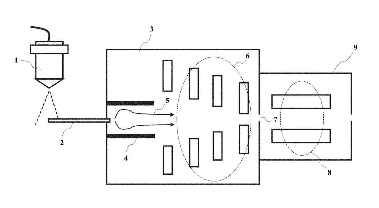
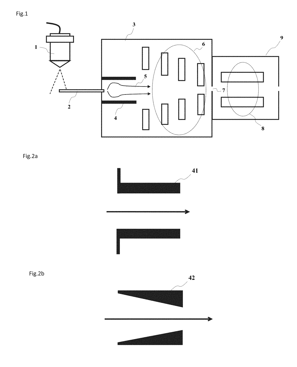
[0044]The present invention is applicable to a device or system for mass spectrographic analysis, such as the mass spectrometer, etc. FIG. 1 is a preferred embodiment of the present invention. Ions generated by an ion source 1 (such as an electrospray ion source, ...


PUM


Abstract

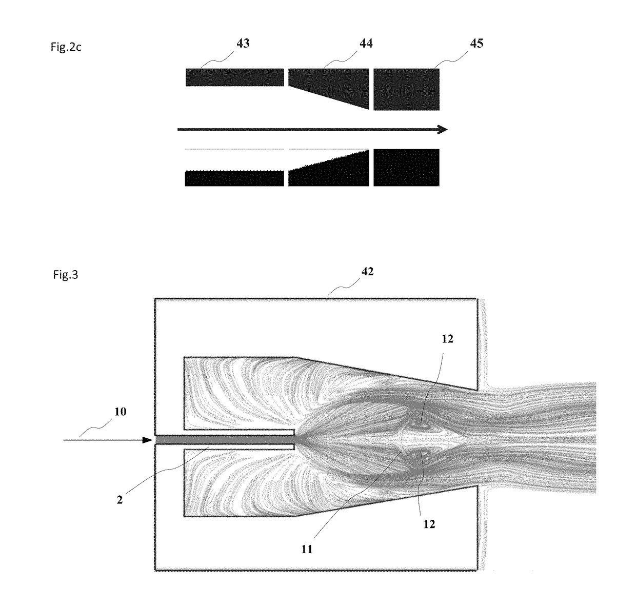
The disclosure relates to a mass spectrometer and a method applied thereby for reducing ion loss and succeeding stage vacuum load. The mass spectrometer includes an ion source connected via vacuum interfaces, a vacuum chamber and a succeeding stage device; wherein a tubular lens is arranged above a Mach disc formed by a gas flow carrying ions at the vacuum interfaces, so that an ion transfer path is restrained and the ions scattering with the gas flow is reduced. In comparison to a sole reliance on a radio-frequency voltage for focusing ions, the efficiency of ion capture in a jet region is improved by using an aerodynamic lens; and the desolvation efficiency of electrically charged droplets is also improved, thereby further improving the sensitivity of the mass spectrometer. Meanwhile, the tubular aerodynamic lens is simple in structure and small in size.

Description

FIELD OF THE INVENTION[0001]The present invention relates to the technical field of mass spectrometry, in particular to a mass spectrometer and a method applied thereby for reducing ion loss and succeeding stage vacuum load.BACKGROUND OF THE INVENTION[0002]A mass analyzer for the mass spectrometer typically works under a certain vacuum degree. Suitable vacuum degree ranges from 10 mtorr to 10−10 torrbased on the type of the analyzer, such as an ion trap, a quadrupole rod, a time of flight type, a Fourier transform type, etc. If the ions to be analyzed are generated in a region of relatively high gas pressure, for example an atmospheric pressure region, a series of vacuum interfaces are required to form a pressure gradient so as to effectively transfer the ions to the region of the analyzer. From the atmospheric pressure to a succeeding stage vacuum (with the gas pressure typically between 10 mtorr and 100 torr), for example, commonly-used vacuum interfaces adopt capillaries, small h...

Claims


Application Information

Patent Timeline
IPC IPC(8): H01J49/06H01J49/24H01J49/04H01J49/10H01J49/26
CPCH01J49/067H01J49/24H01J49/0404H01J49/10H01J49/26
Inventor ZHANG, XIAOQIANGJIANG, GONGYUHUANG, YUNQINGSHEN, JIAQISUN, WENJIAN
Owner SHIMADZU CORP
Learn More