
Optical fiber connection device for a composite structure, composite structure for an aircraft, and manufacturing method thereof

a technology of optical fiber connection and composite structure, which is applied in the direction of optics, fibre mechanical structures, instruments, etc., can solve the problems of difficult industrial implementation and difficulty in achieving the intended integration level, and achieve the effect of simple and cost-effectiv

Active Publication Date: 2018-06-21
AIRBUS OPERATIONS SL
View PDF2 Cites 0 Cited by
  • Summary
  • Abstract
  • Description
  • Claims
  • Application Information

AI Technical Summary

Benefits of technology

The invention provides an optical fiber connection device that can align the optical fibers with minimal loss, resulting in a reliable and robust connection that is resistant to environmental conditions. It also avoids any mechanical degradation or wrinkles on the device's structure.

Problems solved by technology

These smart materials are viable from a theoretical point of view, but are considerably difficult to implement on industrial level.
One of the main problems is on the intermediate face between the different materials, and in the particular case of composite structures with embedded fiber-optic sensors, the problem is in the transition between the composite structures and an external transmitting optical fiber, namely ingress-egress area.
Another problem comes on the area of the composite structure that contains the optical fiber since it presents different geometric and mechanical properties, introducing thereby a particularly delicate point in the composite structure.
Thus, the intended integration level is still a challenge since there are no industrial mature solutions today fulfilling with all main necessary requirements especially with reference to the ingress-egress of the optical fiber.

Method used


Image

  • Optical fiber connection device for a composite structure, composite structure for an aircraft, and manufacturing method thereof
  • Optical fiber connection device for a composite structure, composite structure for an aircraft, and manufacturing method thereof
  • Optical fiber connection device for a composite structure, composite structure for an aircraft, and manufacturing method thereof

Examples


Embodiment Construction

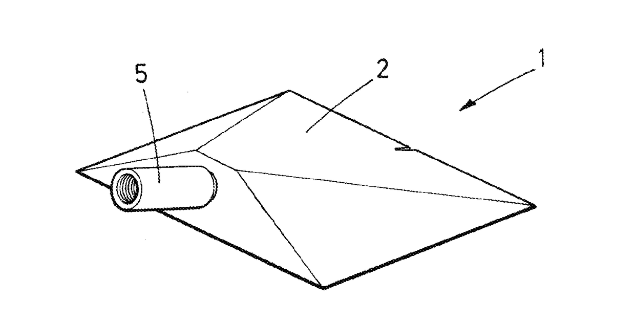
[0046]FIG. 1 shows an optical fiber connection device 1 for a composite structure 20 according to a preferred embodiment.

[0047]FIG. 1c shows a composite structure 20 comprising an optical fiber connection device 1. The optical fiber connection device 1 can be placed at any location on the composite surface, no longer needed, as conventionally, to be placed at one edge of the structure. Thus, the invention is compatible with trimming processes of composite structures.

[0048]According to the invention, the device 1 at least comprises a metallic prism 2, first and second connection elements 3, 4, a closure 5, inner and outer ferrules 11, 12 (FIGS. 6-8), and an elastic element 13 (FIGS. 6-8).

[0049]As shown in FIG. 1, the prism 2 has a planar base 6 for laying on a composite structure 20 in which the input optical fiber 21 is embedded. To allow the connection of the input optical fiber 21 with an outer optical fiber 22, the prism 2 is further provided with an inner conduit 7. The conduit ...


PUM


Abstract

An optical fiber connection device comprising a prism, first and second connection elements, inner and outer ferrules and an elastic element. The prism has an inner conduit ending in a first bore configured to receive an input optical fiber, and in a second bore configured to receive the first connection element, which, in turn, is configured to receive the second connection element. This second connection element is also configured to receive an output optical fiber. The conduit comprises two sections forming a ramp to lead the input optical fiber towards the fibers connection. The first connection element has an inner box, and the second connection element has an outer protrusion to provide a unique connecting position. The inner and outer ferrules, and the elastic element are retained in the second connection element.

Description

CROSS-REFERENCES TO RELATED APPLICATIONS[0001]This application claims the benefit of the European patent application No. 16382635.7 filed on Dec. 21, 2016, the entire disclosures of which are incorporated herein by way of reference.BACKGROUND OF THE INVENTION[0002]The present invention refers to an optical fiber connection device for being used with optical fibers embedded in composite structures. The invention further refers to a composite structure including the optical fiber connection device.[0003]Within the field of structural health monitoring of composite structures, fiber optic-based sensors are increasingly advancing with regard to other conventional instruments, becoming the only solution for some applications. Within the family of fiber optic-based sensors, Bragg network-based sensors are highly used due to their great potential. This technology is particularly being developed for measuring and monitoring structural deformations in different types of structures, such as c...

Claims


Application Information

Patent Timeline
IPC IPC(8): G02B6/38
CPCG02B6/3877G02B6/381G02B6/3849G02B6/3894G02B6/3897G02B6/34G02B6/3833G02B6/3846G02B6/38G02B6/44
Inventor MIGUEL GIRALDO, CARLOSORCHA VILLACORTA, JULIOPATON GUTIERREZ, MANUELJUSDADO SERRANO, CARLOS
Owner AIRBUS OPERATIONS SL
Learn More