Portable electronic device and sensing method thereof
- Summary
- Abstract
- Description
- Claims
- Application Information
AI Technical Summary
Benefits of technology
Problems solved by technology
Method used
Image


Examples
first embodiment
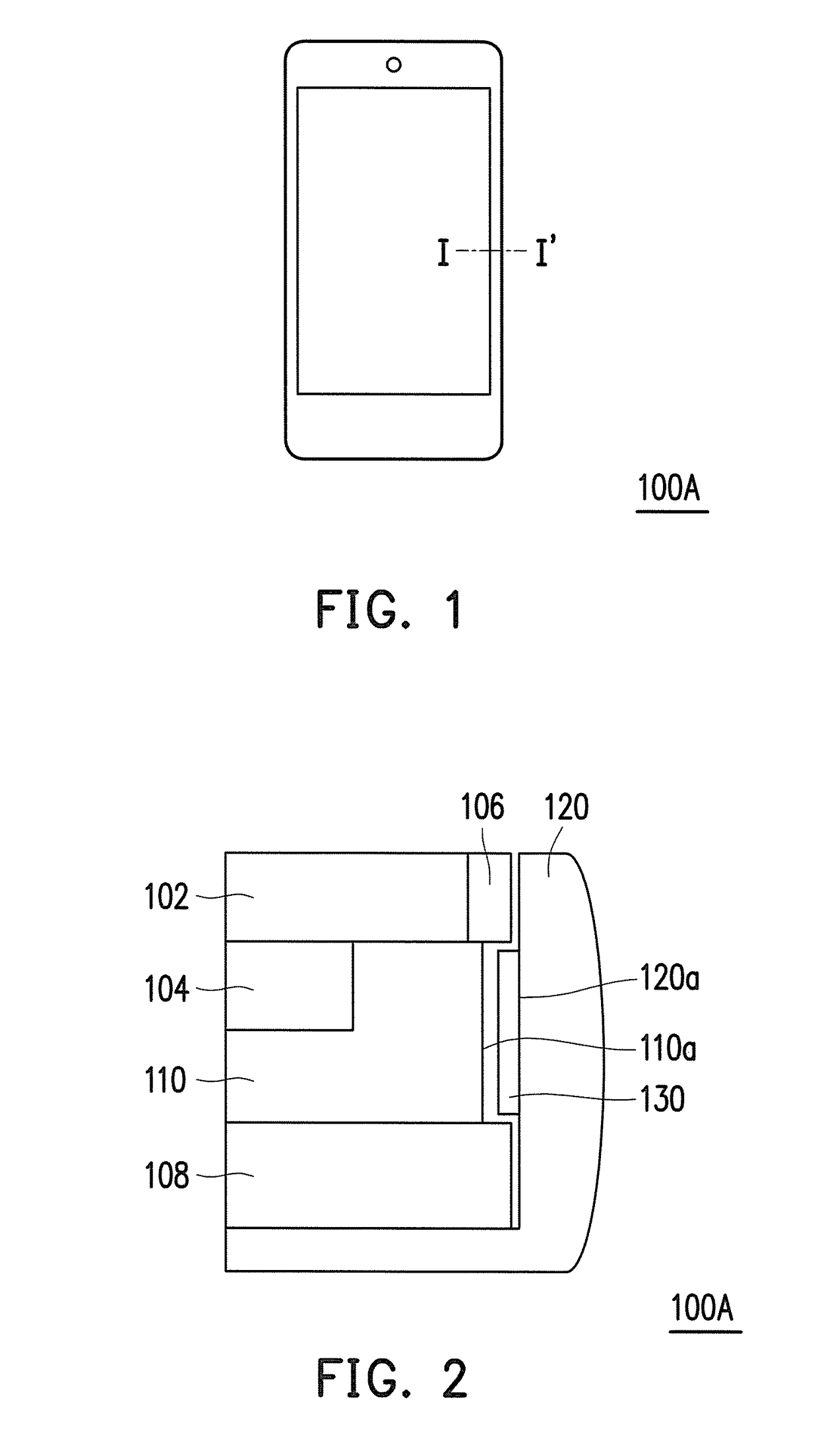
[0024]FIG. 1 is a schematic diagram illustrating a portable electronic device according to the application. FIG. 2 is a partially enlarged view illustrating a cross section along a line I-I′ of FIG. 1. Referring to FIG. 1 and FIG. 2, a portable electronic device 100A of the present embodiment has a sensing function and is adapted for a user to perform command operations by touching. Moreover, the portable electronic device 100A is, for example, a mobile phone or a tablet computer. However, the application is not limited hereto.
[0025]As illustrated in FIG. 2, the portable electronic device 100A of the present embodiment includes a supporting plate 110, a frame 120, and a sensing component 130. The supporting plate 110 has a first sensing side surface 110a. The frame 120 is assembled around the supporting plate 110 and has a second sensing side surface 120a facing the first sensing side surface 110a. The sensing component 130 is disposed between the first sensing side surface 110a and...
second embodiment
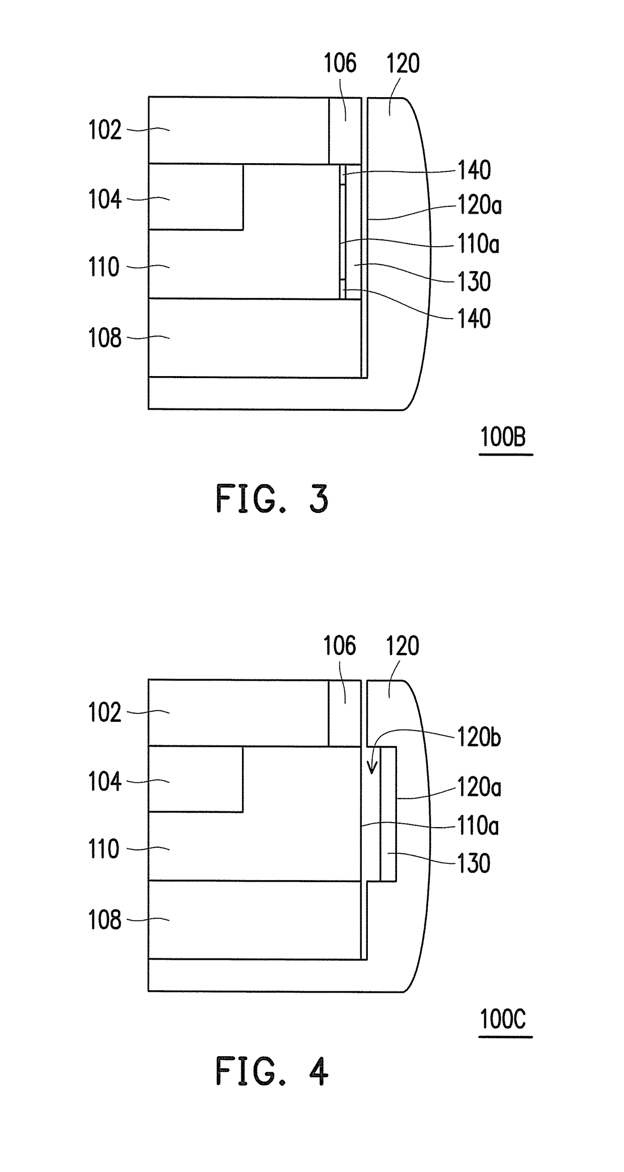
[0027]FIG. 3 is a partially enlarged view illustrating a cross section according to the application. Referring to FIG. 3, the embodiment of FIG. 3 is similar to FIG. 2. The difference is that a portable electronic device 100B of FIG. 3 further includes a buffer component 140. As illustrated in FIG. 3, the buffer component 140 is disposed between the sensing component 130 and the first sensing side surface 110a and is, for example, disposed close to two ends of the sensing component 130. However, the application is not limited hereto. The buffer component 140 is electrically insulative and is, for example, an insulator or a material coated with an insulation film so as not to affect sensing between the sensing component 130 and the first sensing side surface 110a. The buffer component 140 is, for example, a sponge, a double-sided adhesive tape, or another compressible material, so that when the user applies the external force to the frame 120, a variation in the distance between the ...
third embodiment
[0028]FIG. 4 is a partially enlarged view illustrating a cross section according to the application. Referring to FIG. 4, the embodiment of FIG. 4 is similar to FIG. 2. The difference is that the frame 120 of FIG. 4 includes a recess 120b. The sensing component 130 is disposed in the recess 120b and the second sensing side surface 120a is a bottom surface of the recess 120b. In other words, the sensing component 130 is disposed on the bottom surface of the recess 120b. The recess 120b is disposed to correspond to the first sensing side surface 110a, for example, such that the sensing component 130 disposed in the recess 120b can effectively sense the variation in the distance to the first sensing side surface 110a. The application does not limit a depth of the recess 120b. When the user applies the external force to the frame 120, a variation in the distance between the sensing component 130 and the first sensing side surface 110a is generated. Since the sensing component 130 is dis...
PUM
 Abstract
Description
Claims
Application Information
 - R&D
- Intellectual Property
- Life Sciences
- Materials
- Tech Scout
- Unparalleled Data Quality
- Higher Quality Content
- 60% Fewer Hallucinations
Browse by: Latest US Patents, China's latest patents, Technical Efficacy Thesaurus, Application Domain, Technology Topic, Popular Technical Reports.
© 2025 PatSnap. All rights reserved.Legal|Privacy policy|Modern Slavery Act Transparency Statement|Sitemap|About US| Contact US: help@patsnap.com