Modular Power Unit

a module power unit and power supply technology, applied in the field of work machines, can solve the problems of cumbersome access to the various parts and components of the work machine, high number of connections and interface points within the machine, and difficulty in maintenance of the work machin

Active Publication Date: 2018-06-21
CATERPILLAR INC
View PDF1 Cites 0 Cited by
  • Summary
  • Abstract
  • Description
  • Claims
  • Application Information

AI Technical Summary

Benefits of technology

The patent covers three aspects of work machines: a power module with a battery and engine, a drive module with motors, and a hydraulic module for cutting and ripping material. Also, an electric drive machine is included with a front module for cutting and ripping, a power module for power, and a rear module for ripping. Additionally, a power modular device is provided with an engine, battery, and folding heat exchange device for easy access. These aspects allow for improved functionality and efficiency of work machines.

Problems solved by technology

Accordingly, a problem associated with typical work machines is that there often a high number of connections and interface points within the machine.
As such, access to the various parts and components within the work machine may be cumbersome as a result.
Maintenance of the work machine may be more difficult given the number of connections and interface points within the work machine.
It may often be difficult to access and successfully maintain the various parts of the work machine given the high number of connections and interface points within the work machine.
Another problem associated with a work machine that typically has integrated parts and a high number of connection points is that it may be often difficult to remove various parts for service and testing.
Parts which may need service and maintenance such as the engine or battery cannot be separately removed from the work machine while leaving the other parts of the work machine intact.
Further, providing maintenance or testing on either the battery or engine may also involve having to navigate or work around the other parts of the work machine since parts cannot typically be removed from a typical work machine or the like.
Accordingly, the testing of and maintenance of the work machine can be very tedious, cumbersome and time-consuming as a result.
However, such configurations face the common challenge that the all of the parts of the work machine are integrated within the work machine and cannot be separately removed from the work machine.
As a result, such configurations do not address the problem of easy access to parts within the machine, and timely maintenance and testing of the various parts of the work machine.

Method used


Image

  • Modular Power Unit
  • Modular Power Unit
  • Modular Power Unit

Examples


Embodiment Construction

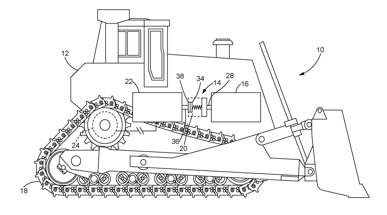
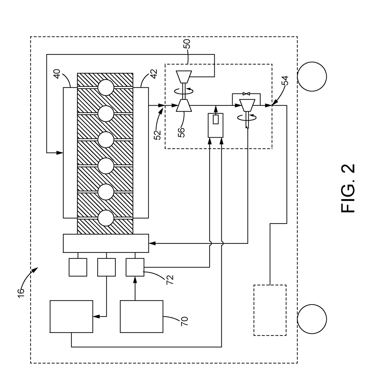
[0025]Referring now to the drawings and with specific reference to FIG. 1, a machine 10 is depicted. With continued reference to FIG. 1, the machine 10 may be an electrically powered track-type tractor 10, truck, earth-moving machine, work machine or the like. The machine 10 is illustrated in the context of a track type machine that may be used in construction, mining, road building, or the like. The machine 10 is nevertheless not limited to just performing construction, mining, or road building, and may be used for other purposes. The machine 10 may include a mobile electric drive machine having a frame 12. The frame 12 may have an electrical power system 14 mounted therein. The electrical power system 14 may include an engine 16 that provides electrical power for the machine 10. The machine 10 may also include one or more tracks 18. The machine 10 may also include a drive coupling 20 between the engine 16 and a generator 22. An electric motor 24 may be provided that is coupled to ...


PUM


Abstract

A work machine is provided. The work machines may include a power module configured to provide power including a battery and an engine and configured to a folding heat exchange device. The work machine may also include a drive module configured with one or more motors and positioned over a track roller frame. The work machine may also include a hydraulic module including one or more devices in a front region and one or more devices in a rear region to cut or rip encountered material

Description

TECHNICAL FIELD[0001]The present disclosure generally relates to work machines and, more particularly, relates to cab-less autonomous track-type tractors.BACKGROUND[0002]Track-type tractors, earth-moving machines and other work machines generally may contain parts which are often integrated as one self-contained assembly. Many parts of the work machine are often used to perform certain functioning. For instance, a blade and ripping unit at the front and back of the work machine, respectively, may be configured to cut and rip material encountered by the work machine on its path. A power unit within the work machine may include a battery and an engine and may provide the power within the work machine.[0003]In typical work machines or track-type tractors, the parts described above may often be integrated with the work machine, wherein the entire work machine may be one self-contained assembly in which the parts of the work machine cannot be separated from another or separately removed ...

Claims


Application Information

Patent Timeline
IPC IPC(8): F28F5/00E02F3/76E02F3/815E02F9/28E02F9/08F02B61/00F02B37/00
CPCF28F5/00E02F3/7609E02F3/815E02F9/2875F28F2280/10F02B61/00F02B37/00E02F9/2275F28F2280/105E02F9/0833E02F3/7604E02F5/32E02F9/0866F02B77/00F02B2201/00Y02E30/00Y02T10/12G21C19/42G21D5/02G21H3/00
Inventor BRAUER, MATTWYSS, JACOB CARL
Owner CATERPILLAR INC
Why Eureka
Try Eureka