
System and method for monitoring blade deflection of wind turbines

a technology of wind turbines and blades, applied in the direction of testing/monitoring control systems, program control, instruments, etc., can solve the problems of low precision of wind turbines, exposed equipment (especially cabling), and inability to meet all operating conditions of wind turbines. the desired level of precision and reliability cannot be achieved

Active Publication Date: 2018-06-21
INSTITUT NATIONAL D'OPTIQUE +1
View PDF17 Cites 16 Cited by
  • Summary
  • Abstract
  • Description
  • Claims
  • Application Information

AI Technical Summary

Benefits of technology

The patent describes a system for monitoring the deflection of turbine blades in a wind turbine. The system includes a position detecting apparatus mounted to the wind turbine and a deflection controller. The position detecting apparatus has multiple sensors that detect the presence or absence of segments of the turbine blades. The system uses the detected presence or absence to determine the distance of each segment from the tower, which is representative of the deflection of the blades. The system can also detect the angular position of the turbine blades and can use this information to determine the clearance of the blades. The system can also use data from other sensors, such as inclinometers and accelerometers, to monitor the blades. The system can also trigger corrective actions to prevent the blades from hitting the tower. Overall, the system allows for effective monitoring of the deflection of wind turbine blades and ensures optimal performance of the wind turbine.

Problems solved by technology

The installation of gauges and the installation of their electrical cabling needed are expensive, especially beside a wind turbine which is in operation.
The equipment (especially the cabling) is exposed to lightning strikes, thus the gauges are mainly used for time-limited test purposes.
Thus, none of these solutions provides the desired level of precision nor provides the reliability to face all operating conditions of a wind turbine.

Method used


Image

  • System and method for monitoring blade deflection of wind turbines
  • System and method for monitoring blade deflection of wind turbines
  • System and method for monitoring blade deflection of wind turbines

Examples


Embodiment Construction

[0044]Reference now will be made in detail to embodiments of the present subject matter, one or more examples of which are illustrated in the drawings. Each example is provided by way of explanation, without limiting the scope of the present subject matter. In fact, it will be apparent to those skilled in the art that various modifications and variations can be made in the present subject matter without departing from its scope or spirit. For instance, features illustrated or described as part of one embodiment can be used with another embodiment to yield a still further embodiment. Thus, it is intended that the present subject matter covers such modifications and variations as come within the scope of the appended claims and their equivalents.

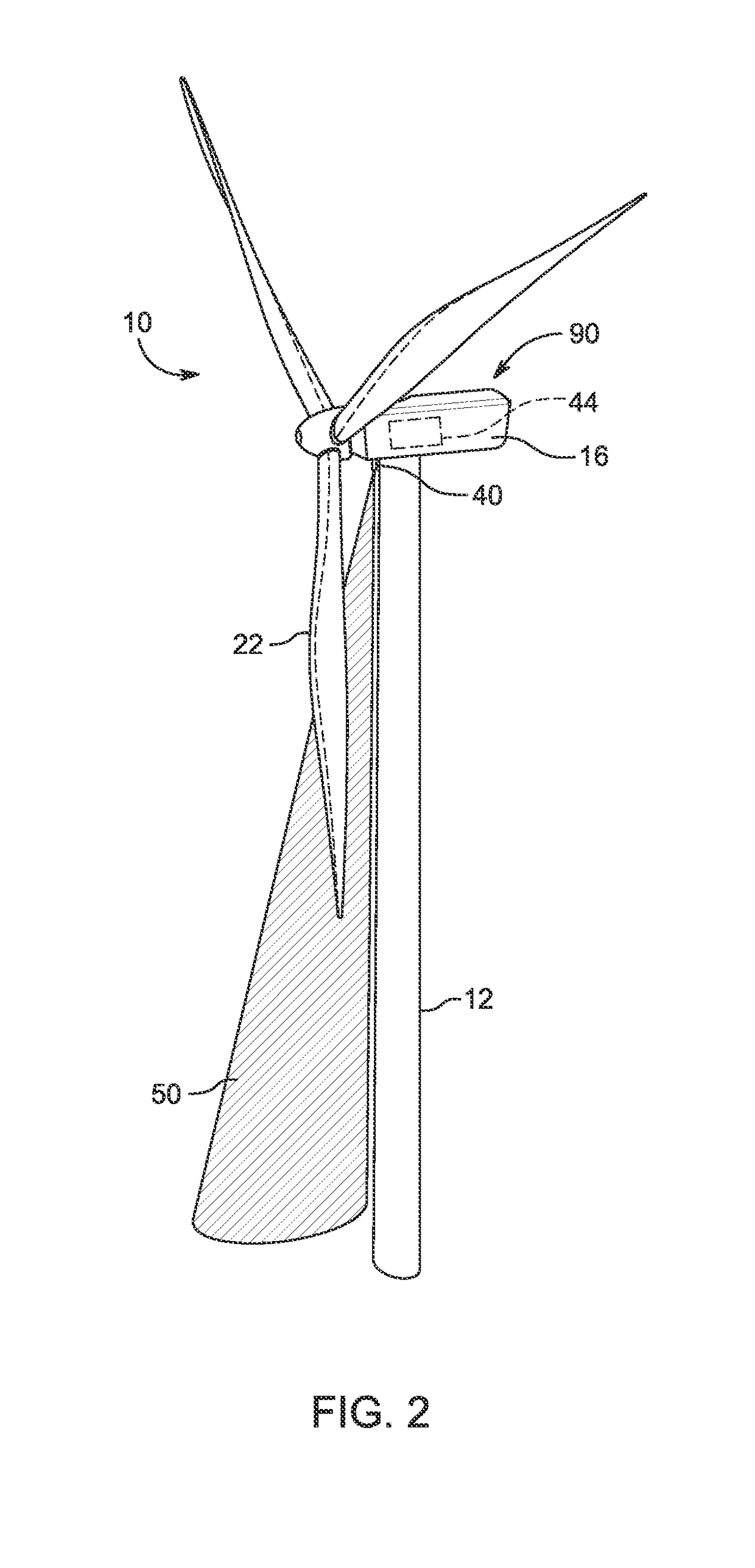
[0045]FIG. 1 illustrates a perspective view of a wind turbine 10. As shown, the wind turbine 10 is a horizontal-axis wind turbine. The wind turbine 10 comprises a tower 12 (or a post) that extends from a base 14, a nacelle 16 mounted on the to...


PUM


Abstract

Described is a system for monitoring deflection of turbine blades of a wind turbine comprising a tower. The system comprises a position detecting apparatus mounted to the wind turbine comprising a plurality of position detection components each collecting data regarding a field of detection through which a segment of the turbine blades passes, wherein the position detection components are monitoring distinct fields of detection to collect distances of a plurality of segments of each one of the turbine blades travelling through the fields of detection. The system further comprises a deflection controller configured to receive the collected distances and to determine deflection of the turbine blades accordingly. An associated method comprises collecting distances of a plurality of distinct segments of the turbine blades when the turbine blades travel within a plurality of fields of detections, and processing the collected distances to determine clearance between the turbine blades and the tower.

Description

CROSS-REFERENCE TO RELATED APPLICATION[0001]This application claims priority from U.S. patent provisional application 62 / 435,189 filed Dec. 16, 2016, the specification of which is hereby incorporated herein by reference in its entirety.BACKGROUND(a) Field[0002]The invention relates to an arrangement to monitor the deflection or bending of an object, preferably to monitor the deflection or bending of a wind-turbine blade.(b) Related Prior Art[0003]Blades of modern wind turbines are quite long; they may measure up to 88 meters long or even more. Thus, their shape and their characteristics need to be monitored in order to optimize their aerodynamic profile by adjusting the blade pitch angle, especially to prevent sudden change in loads that could cause damage to one or multiple blades either by reaching critical deflection or by hitting the tower while the wind turbine is in operation.[0004]More specifically, the deflection or bending of the blade near its tip-end needs to be known to ...

Claims


Application Information

Patent Timeline
Patent Type & Authority Applications(United States)
IPC IPC(8): F03D17/00F03D7/02G05B19/048
CPCF03D17/00F03D7/0224F03D7/0244F03D7/0204G05B19/048F03D1/06F05B2270/33F05B2270/804F05B2240/912G05B2219/2619F03D7/0288F05B2270/17Y02E10/728G05B23/0289F05B2270/8042Y02E10/72F05B2240/302
Inventor DAVID, VINCENTCANTIN, DANIELGUILLEMETTE, ROBERTCLOUTIER, JONATHAN
Owner INSTITUT NATIONAL D'OPTIQUE
Learn More