
Vascular intervention robot and vascular intervention system

a vascular intervention and robot technology, applied in the field of vascular intervention robots and vascular intervention systems, can solve the problems of operating room operators being exposed to radiation during vascular intervention for a long time, and achieve the effect of easy attachment and detachment, and high degree of freedom

Active Publication Date: 2018-06-21
PERAZAH INC
View PDF0 Cites 20 Cited by
  • Summary
  • Abstract
  • Description
  • Claims
  • Application Information

AI Technical Summary

Benefits of technology

The patent text describes a vascular intervention robot that has easily attachable and detachable components. The robot also has a high degree of freedom and may include a fixing pin to prevent the fitting part from escaping. The technical effects of the invention include improved flexibility and ease of use for the vascular intervention robot.

Problems solved by technology

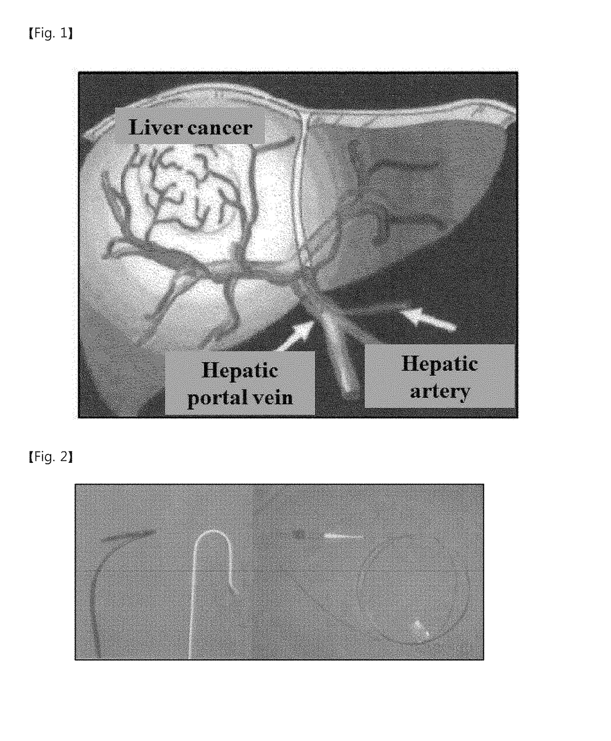
Thus, the operator is exposed to radiation during the vascular intervention for a long time.

Method used


Image

  • Vascular intervention robot and vascular intervention system
  • Vascular intervention robot and vascular intervention system
  • Vascular intervention robot and vascular intervention system

Examples


first embodiment

[0067]A vascular intervention robot according to the inventive concepts will be described hereinafter.

[0068]Vascular Intervention Robot

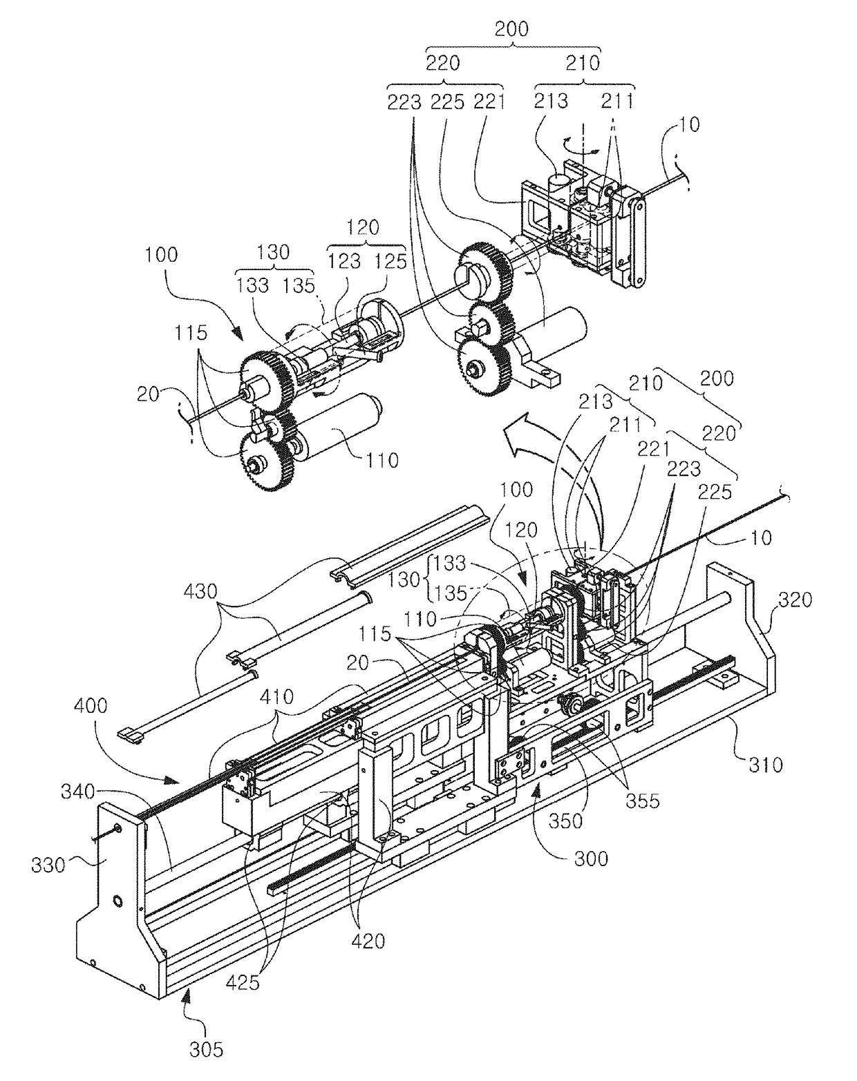
[0069]Since the guide wire and the catheter should be inserted and rotated, the vascular intervention robot needs 4 degrees of freedom. FIG. 6 shows a mechanism of a catheter driven in 4 degrees of freedom. A three-stage telescope structure was designed to realize co-axial motion of the guide wire and the catheter. This telescope structure prevents the guide wire and the catheter from sagging. To easily attach or install an existing surgical tool to the robot by a medical doctor, the telescope structure was designed in such a way that lower and upper components are vertically separated from each other and then the upper component is assembled with the lower component to cover the catheter after the catheter is located on the lower component (see FIG. 7). This separate assembly design has the advantage in disinfection.

[0070]The catheter and a surgical...

second embodiment

[0095]FIGS. 20, 21 and 22 show a perspective view, a side view and a plan view of a vascular intervention robot according to the inventive concepts, respectively. The vascular intervention robot of FIGS. 20 to 22 will be described with further reference to FIGS. 23 to 29.

[0096]The vascular intervention robot according to the second embodiment of the inventive concepts may include at least one of a catheter rotation unit 600, a guide wire rotation and supply unit 700, a transfer unit 800, and a catheter guide unit 900. In addition, the vascular intervention robot may provide rotational motion and translational motion to a catheter 20 and a guide wire 10 in a state in which the catheter 20 and the guide wire 10 are provided in a co-axial system. In the following descriptions, the catheter 20 of the second embodiment corresponds to the catheter 20 of the first embodiment, and the guide wire 10 of the second embodiment corresponds to the guide wire 10 of the first embodiment. Hereinafte...


PUM


Abstract

A vascular intervention robot includes a catheter rotation unit for rotating a catheter on an axis parallel to a longitudinal direction of the catheter, a guide wire rotation and supply unit that is provided at one side of the catheter rotation unit and that is provided for transferring a guide wire in a longitudinal direction of the guide wire and for rotating the guide wire on an axis parallel to the longitudinal direction of the guide wire in a state in which the guide wire is inserted in the catheter, a transfer unit for transferring the catheter rotation unit and the guide wire rotation and supply unit in the longitudinal direction of the catheter, and an expanding and contracting unit that is provided at another side of the catheter rotation unit and that is expandable and contractible along the longitudinal direction of the catheter while supporting the catheter when the transfer unit transfers the catheter rotation unit and the guide wire rotation and supply unit in the longitudinal direction of the catheter.

Description

CROSS-REFERENCE TO RELATED APPLICATION[0001]This application is a continuation of pending International Application No. PCT / KR2016 / 005857, which was filed on Jun. 2, 2016 and claims priority to Korean Patent Application Nos. 10-2015-0085253 and 10-2015-0089044, filed on Jun. 16, 2015 and Jun. 23, 2015, in the Korean Intellectual Property Office, the disclosures of which are hereby incorporated by reference in their entireties.BACKGROUND1. Field[0002]Embodiments of the inventive concepts relate to a vascular intervention robot and a vascular intervention system and, more particularly, to a vascular intervention robot and a vascular intervention system, which facilitate disinfection and replacement of components by simplifying a detachable structure.2. Description of the Related ArtVascular Intervention[0003]The vascular intervention is a minimally invasive surgery for curing vascular disease or cancer. In the vascular intervention, a small catheter having a diameter of several mm or ...

Claims


Application Information

Patent Timeline
Patent Type & Authority Applications(United States)
IPC IPC(8): A61B34/30A61B34/37A61M25/01A61M25/09
CPCA61B34/30A61B34/37A61M25/0113A61M25/0116A61M25/09041A61B2034/303A61B2034/301A61M2210/12A61B90/00A61B2090/571
Inventor YI, BYUNGJUCHA, HYOJEONGJUNG, KWANYOUNGWON, JONGYOON
Owner PERAZAH INC
Learn More