
Signal processing in an optical receiver

a technology of optical receiver and signal processing, applied in the direction of radio transmission, electrical apparatus, transmission, etc., can solve the problems of increasing the cost of precision dependent analog circuitry design, exacerbate the problem, severe degrade the performance of the receiver when using high-order modulation formats, etc., and achieve the effect of no practical effect on the performance of the adaptation loop

Active Publication Date: 2018-06-07
XIEON NETWORKS SARL
View PDF0 Cites 10 Cited by
  • Summary
  • Abstract
  • Description
  • Claims
  • Application Information

AI Technical Summary

Benefits of technology

The patent describes a method for equalizing optical signals in a communication system, using a technique called MIMO equalization. The method compensates for chromatic dispersion and other distortions in the signal using coefficients that are adjusted based on signals from a carrier recovery module. The adjusted coefficients are then used to equalize the signals. The method allows for independent adjustment of the coefficients for each signal, ensuring accurate compensation for time misalignment. The resulting delay in the feedback path is negligible, and the method can be implemented using existing algorithms. Additionally, the method includes compensating for chromatic dispersion in multiple signals simultaneously, allowing for more efficient and accurate equalization.

Problems solved by technology

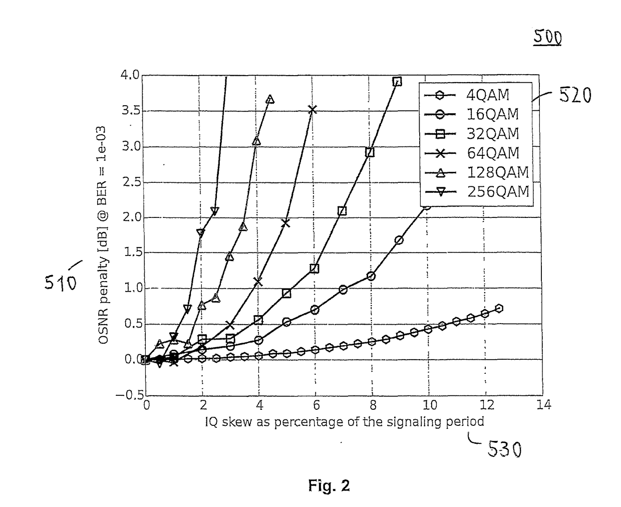
In particular, imbalances in the length of the receiver paths result in timing misalignments (skew) between HI and HQ or VI and VQ, which can severely degrade the performance of the receiver when using high-order modulation formats.
Additionally, the emerging trend towards higher symbol rates is going to exacerbate the problem.
However, such precision dependent analog circuitry design becomes increasingly prohibitive as the constellation size and the signaling rate grow.
Moreover, it is difficult, if not impossible, to predict skew effects arising in such ADCs, which further complicates the analog circuitry design, and can even prevent the appropriate dimensioning of strip lines on the printed circuit board.
A significant disadvantage of this approach is that the respective calibration routine can be time-consuming and dedicated components (capture facility after the ADCs and configurable fractional delays) are required, which increases the complexity of the circuit and digital processor, and also increases the related power consumption.
Further, this approach provides a fixed, non-adaptive, compensation, which can be inadequate for many demanding modulation formats.
However, merging both equalization stages into one stage requires the implementation of an adaptive MIMO equalizer including 500-4000 (instead of 1-40) taps, which is impractical.
On the one side, the adaptation of such a large number of tap coefficients runs into huge convergence difficulties; and on the other side, the use of a 4×4 bulk CD MIMO equalizer results in double complexity with respect to the state-of-the-art solution having two complex 1×1 bulk CD equalizers.
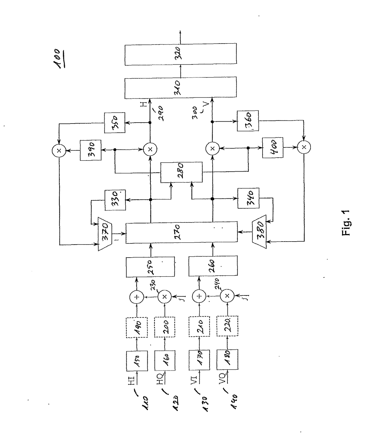
However, a significant disadvantage of the arrangement shown in FIG. 4 is that the complex 4×2 MIMO equalizer 790 requires twice as many computations as the standard complex 2×2 MIMO equalizer 270 of FIG. 1 or the real 4×4 MIMO equalizer 610 of FIG. 3.

Method used


Image

  • Signal processing in an optical receiver
  • Signal processing in an optical receiver
  • Signal processing in an optical receiver

Examples


Embodiment Construction

[0051]For the purposes of promoting an understanding of the principles of the invention, reference will now be made to the preferred embodiments illustrated in the drawings and specific language will be used to describe the same. It will nevertheless be understood that no limitation of the scope of the invention is thereby intended, such alterations and further modifications in the illustrated devices and method and such further applications of the principles of the invention as illustrated therein being contemplated therein as would normally occur now or in the future to one skilled in the art to which the invention relates.

[0052]FIGS. 1 to 4 provide background information and illustrate examples of digital signal processing devices according to the state-of-the-art; see discussion above.

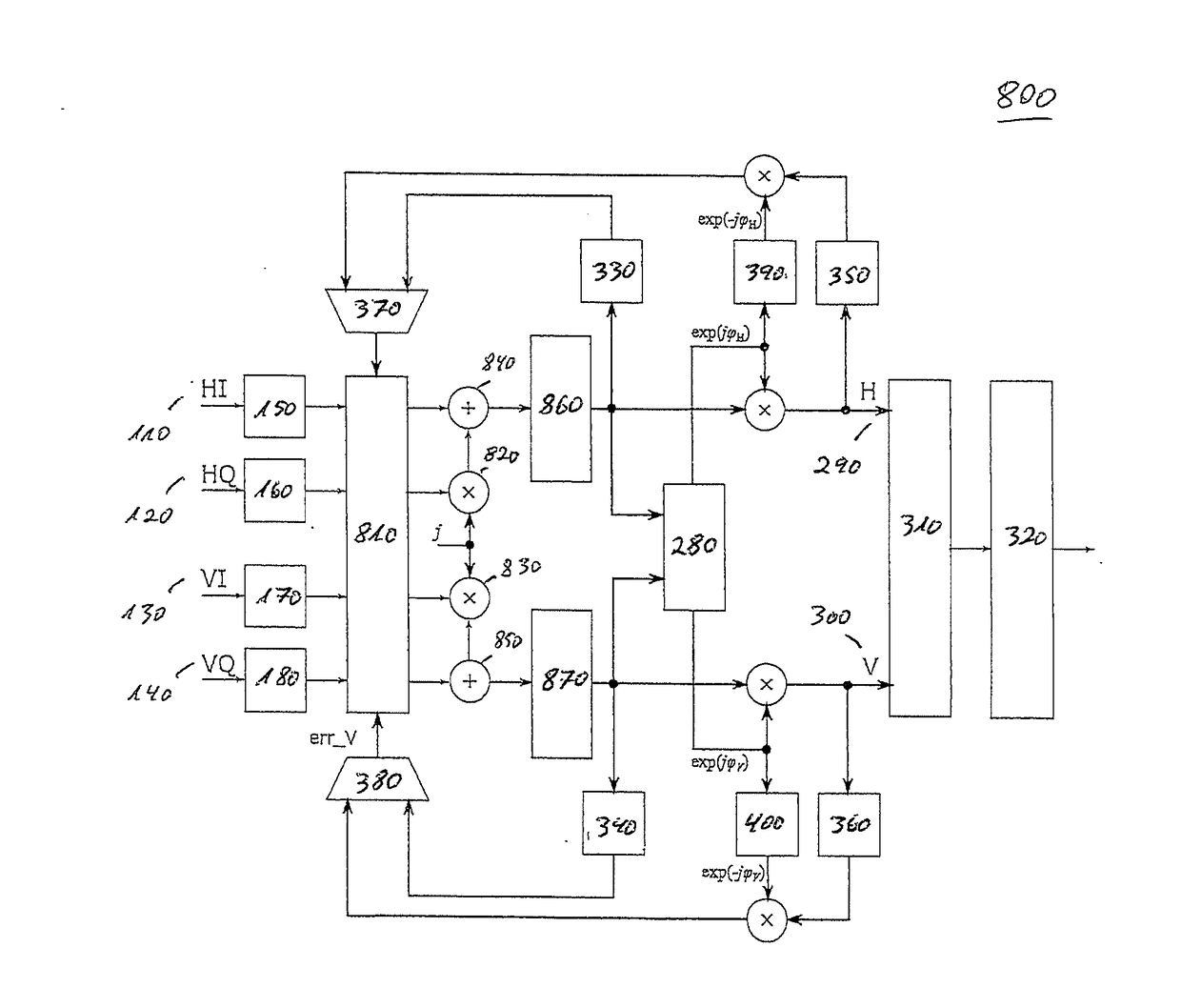
[0053]FIG. 5 illustrates a digital signal processing device 800 according to an embodiment of the present invention. In this embodiment, the analog-to-digital converters 150, 160, 170, 180 convert ...


PUM


Abstract

The present invention relates to signal processing in an optical receiver, in particular to equalization performed in coherent optical receivers. A multiple-input multiple-output (MIMO) equalizer receives and equalizes a plurality of real value signals, for example four sampled electrical baseband tributaries (HI, HQ, VI, VQ). The outputs of the multiple-input multiple-output (MIMO) equalizer provide equalized real or imaginary components of complex signals. The complex signals including the real and imaginary components are then each and individually equalized to remove chromatic dispersion.

Description

FIELD OF THE INVENTION[0001]The present invention relates to the field of signal processing in an optical receiver, in particular to equalization performed in coherent optical receivers. The present invention comprises a signal processing device including a plurality of chromatic dispersion equalizers and a multiple-input multiple-output equalizer, wherein the chromatic dispersion equalizers are configured to receive and equalize signals provided by the multiple-input multiple-output equalizer. Moreover, the present invention relates to a corresponding signal processing method.BACKGROUND OF THE INVENTION[0002]Conventional coherent receivers in optical communication systems make use of channel equalizers to mitigate channel impairments. For example, equalizer stages can be implemented to provide a digital detector with the capability to correct channel impairments.[0003]In this respect, modern optical communication systems can employ multi-phase multi-level signal alphabets and polar...

Claims


Application Information

Patent Timeline
Patent Type & Authority Applications(United States)
IPC IPC(8): H04J14/06H04B10/61H04B7/0413H04B10/69
CPCH04J14/06H04B10/6165H04B10/6162H04B7/0413H04B10/6971H04B10/2569H04B10/6161
Inventor CALABRO, STEFANOSPINNLER, BERNHARD
Owner XIEON NETWORKS SARL
Learn More