
Filter that minimizes in-band noise and maximizes detection sensitivity of exponentially-modulated signals

a filter and exponential modulation technology, applied in the field of filters that minimize in-band noise and maximize the detection sensitivity of exponential modulation signals, can solve the problems of no threshold, no linearity, and limited filter performance of devices

Active Publication Date: 2018-06-07
DYNASPOT
View PDF4 Cites 0 Cited by
  • Summary
  • Abstract
  • Description
  • Claims
  • Application Information

AI Technical Summary

Benefits of technology

The patent describes a filter that can demodulate an exponentially-modulated signal with noise in its signal band. The filter has parallel paths that delay the signal and a time delay for each path. The delayed signals are then combined to generate an output that is a function of the rate change of the carrier frequency. The output contains impulses for abrupt changes in the carrier frequency. The filter can be used with any modulation format of the exponentially-modulated signal and can compress noise in the signal band. The technical effect of this invention is to improve the demodulation of exponentially-modulated signals with noise.

Problems solved by technology

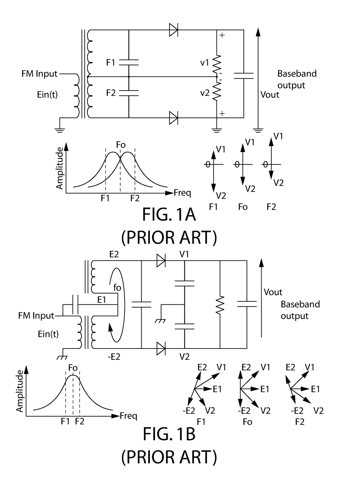
However, such devices introduce non-linearities, e.g., noise cross products, that are the root cause of the threshold phenomenon.
This class of detectors do not convert AWGN to a parabolic noise power distribution.
The multipliers or mixers used to perform the conversion do not transform flat input noise density to parabolic and so are limited to matched filter performance.
However, there is no threshold if the band can be made small enough.
Therefore, in view of the foregoing, all of these conventional demodulators fail to address the CNR threshold and, as a result, at or below this threshold the output signal is pure noise.
Furthermore, because these configurations are demodulators, they do not operate as filters and consequently these demodulators cannot be cascaded.

Method used


Image

  • Filter that minimizes in-band noise and maximizes detection sensitivity of exponentially-modulated signals
  • Filter that minimizes in-band noise and maximizes detection sensitivity of exponentially-modulated signals
  • Filter that minimizes in-band noise and maximizes detection sensitivity of exponentially-modulated signals

Examples


Embodiment Construction

[0053]Referring now to the figures, wherein like reference numerals represent like parts throughout the several views, exemplary embodiments of the present disclosure will be described in detail. Throughout this description, various components may be identified having specific values, these values are provided as exemplary embodiments and should not be limiting of various concepts of the present invention as many comparable sizes and / or values may be implemented.

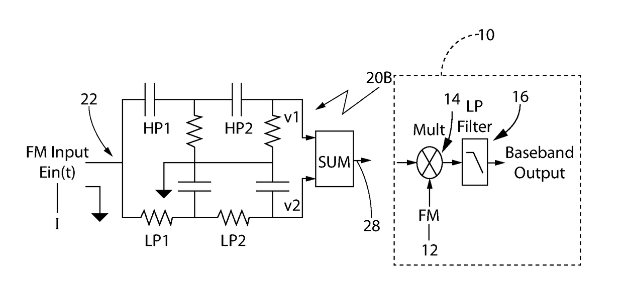
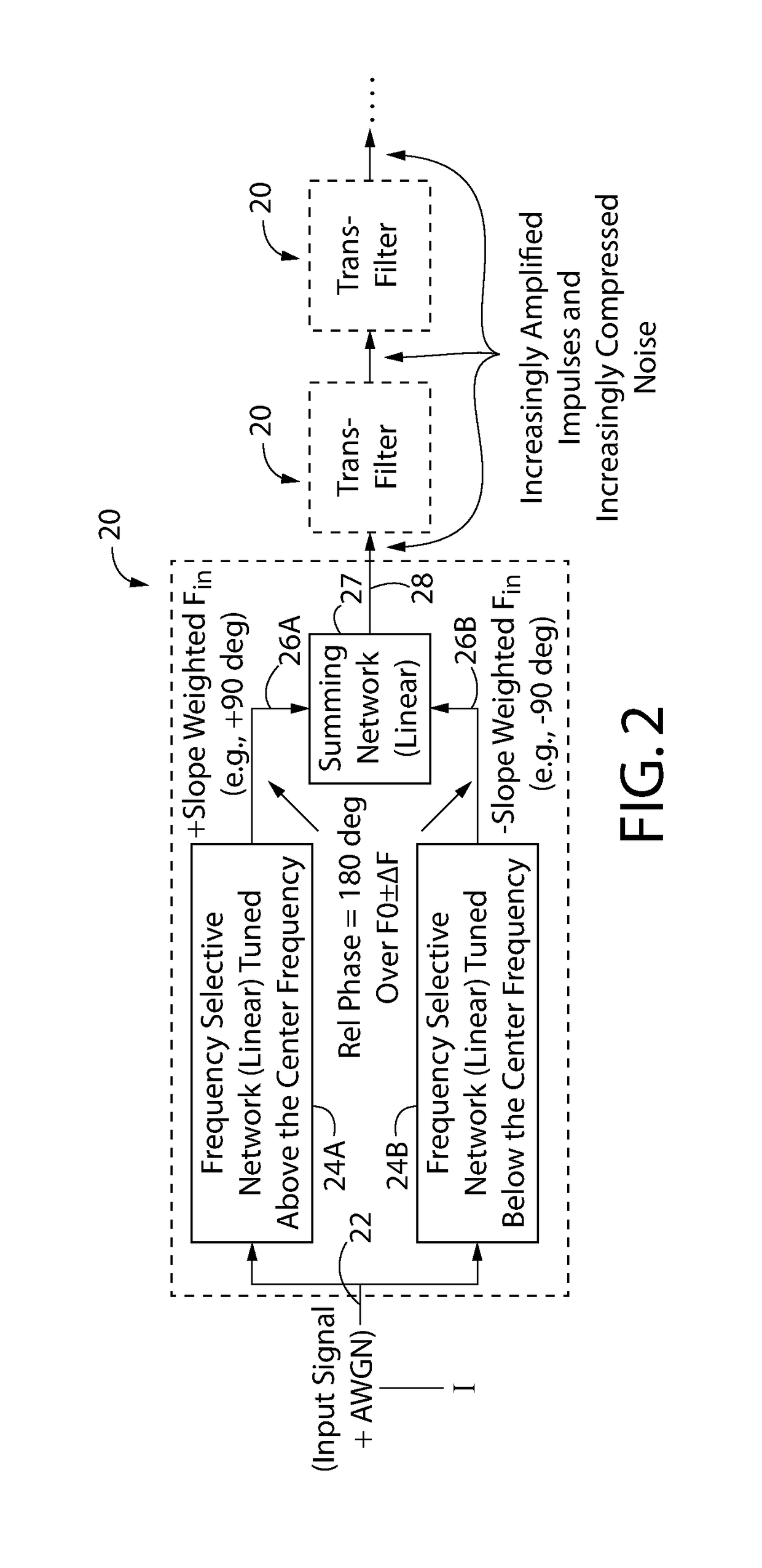
[0054]The trans-filter 20 minimizes in-band noise and maximizes detection sensitivity of exponentially-modulated signals 20 by eliminating the threshold phenomenon that limits detection sensitivity of exponentially modulated signals (also referred to as “angle modulated signals”). It accomplishes this by elimination of nonlinear circuit elements (e.g., diodes, transistors, non-linear magnetics, etc.) used in conventional exponential modulation detectors such as phase or frequency discriminators.

[0055]The filter 20 is a linea...


PUM


Abstract

Frequency domain (FDTF) and time domain (TDTF) trans-filters compress in-band AWGN, demodulate input signals and have no threshold due to applied noise. Two parallel frequency selective networks with opposite amplitude vs frequency slopes are designed to remain 180 degrees out of phase over the signal band in the FDTF whereas two parallel delay networks are used in the TDTF. Output amplitudes are equal at band center and are summed producing a monotonic amplitude vs frequency characteristic going thru zero at center frequency with abrupt phase reversal. This produces the parabolic output noise density and differentiates applied signals. Absence of nonlinear circuit components and product devices prevents generation of noise×noise products, avoiding the threshold phenomenon. Exponentially modulated digital signals produce output impulses due to the slope and abrupt phase reversal. The impulses have strong fundamental frequency components and may be recovered at baseband without frequency conversion. Cascading trans-filters increases noise reduction and impulse amplitude. The trans-filter algorithm may be used separately or in conjunction with one or more hardware trans-filters.

Description

CROSS-REFERENCE TO RELATED APPLICATIONS[0001]This Continuation-in-Part application claims the benefit under 35 U.S.C. § 120 of application Ser. No. 15 / 127,472 filed on Sep. 20, 2016, which in turn claims the benefit under 35 U.S.C. § 371 of International Application No. PCT / US2015 / 021675 filed on Mar. 20, 2015, all of which are entitled A FILTER THAT MINIMIZES IN-BAND NOISE AND MAXIMIZES DETECTION SENSITIVITY OF EXPONENTIALLY-MODULATED SIGNALS, and which in turn claims the benefit under 35 U.S.C. § 119(e) of Provisional Application Ser. No. 61 / 968,453 filed on Mar. 21, 2014 entitled TRANS FILTER and all of whose entire disclosures are incorporated by reference herein.BACKGROUND OF THE INVENTION[0002]The present invention relates generally to devices that recover, detect or demodulate signals, and more particularly, to devices that provider greater sensitivity and noise rejection for the detection of FM Doppler radar, geological or oceanographic sonar returns and for spread spectrum ...

Claims


Application Information

Patent Timeline
IPC IPC(8): H03H17/02H04B1/16G06F7/50
CPCH03H17/0219H04B1/16H03H17/0283G06F7/50H03D3/06H03H7/06H03H17/0264H03D2200/0054
Inventor SASSLER, MARVIN L.SASSLER, ALAN T.
Owner DYNASPOT
Learn More