
Method and system for determining encoding parameters of video sources in large scale video surveillance systems

a video surveillance system and video source technology, applied in the field of video surveillance systems, can solve the problems of manufacturer-dependent configuration, difficult inconvenient installation of network cameras, so as to achieve the effect of convenient installation and setting

Active Publication Date: 2018-05-31
CANON KK
View PDF2 Cites 10 Cited by
  • Summary
  • Abstract
  • Description
  • Claims
  • Application Information

AI Technical Summary

Benefits of technology

The invention provides a method and device that can automatically or semi-automatically determine the optimal configuration of a video source during different tasks, without requiring specific knowledge from an administrator. This makes it easier and quicker to install and set up a video surveillance system. Additionally, the invention includes a step of generating a look-up table to determine the likely configuration of a video source based on its output, independently of its theoretical characteristics.

Problems solved by technology

Configuring a network camera is not easy.
In particular, setting the video stream encoders of the network camera can be complex for users that are not familiar with each type of network camera.
Such a complexity results from the great number of parameters that may for example comprise a video resolution, a video codec, a bitrate control, a frame rate, a video quality, and a Group of Pictures (GoP).
It also results from the technical nature of these parameters and from their impacts that are not directly known and visible to the one setting the parameters, for example in terms of image quality, network bandwidth, and resource consumption.
Moreover, while the format of the outputs of the encoders generally conforms to a standard, the manufacturers implement their own encoders, resulting in manufacturer-dependent configuration.
As a consequence, an administrator or the one who is in charge of configuring the encoders doesn't know which encoder is embedded in a given camera and thus cannot make an a priori determination of an optimal configuration.
The problem is complex for a given network and becomes even difficult and quite unrealistic in large scale video surveillance systems, in terms of complexity and worktime.

Method used


Image

  • Method and system for determining encoding parameters of video sources in large scale video surveillance systems
  • Method and system for determining encoding parameters of video sources in large scale video surveillance systems
  • Method and system for determining encoding parameters of video sources in large scale video surveillance systems

Examples


Embodiment Construction

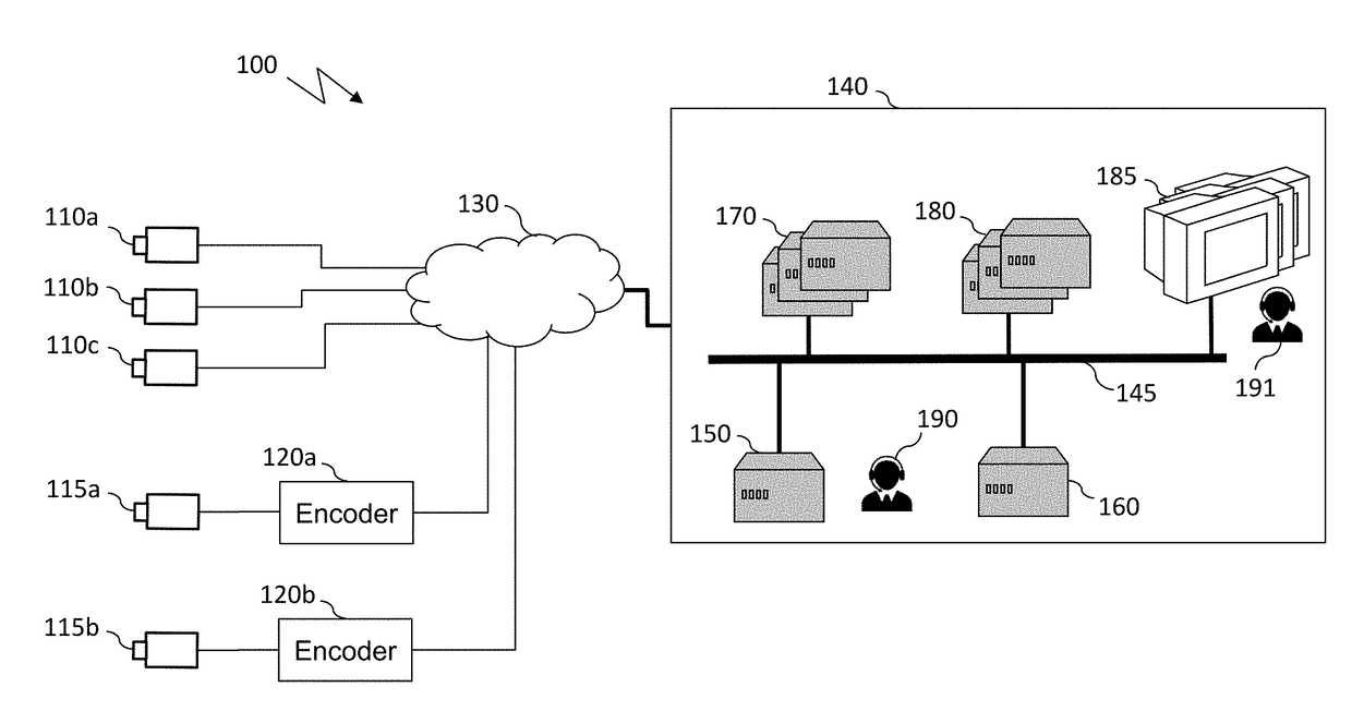
[0071]FIG. 1 schematically illustrates an example of a video surveillance (VS) system wherein embodiments of the invention may be implemented.

[0072]VS system 100 includes a plurality of network cameras denoted 110a, 110b, and 110c, for example network cameras of the Internet Protocol (IP) type, generically referred to as IP cameras 110, and a plurality of video encoders denoted 120a and 120b, generally referred to as video encoders 120, which may connected to one or more network cameras, for example to IP or analog cameras 115a and 115b.

[0073]Network cameras 110 and video encoders 120 are referred to as source devices that can be identified by a manufacturer reference and a model reference. Two source devices are considered similar if they have been made by the same manufacturer and if they are of the same model. Otherwise, they are considered as different.

[0074]Each source device embeds at least one video encoder which is referred to as a source video encoder. From an implementati...


PUM


Abstract

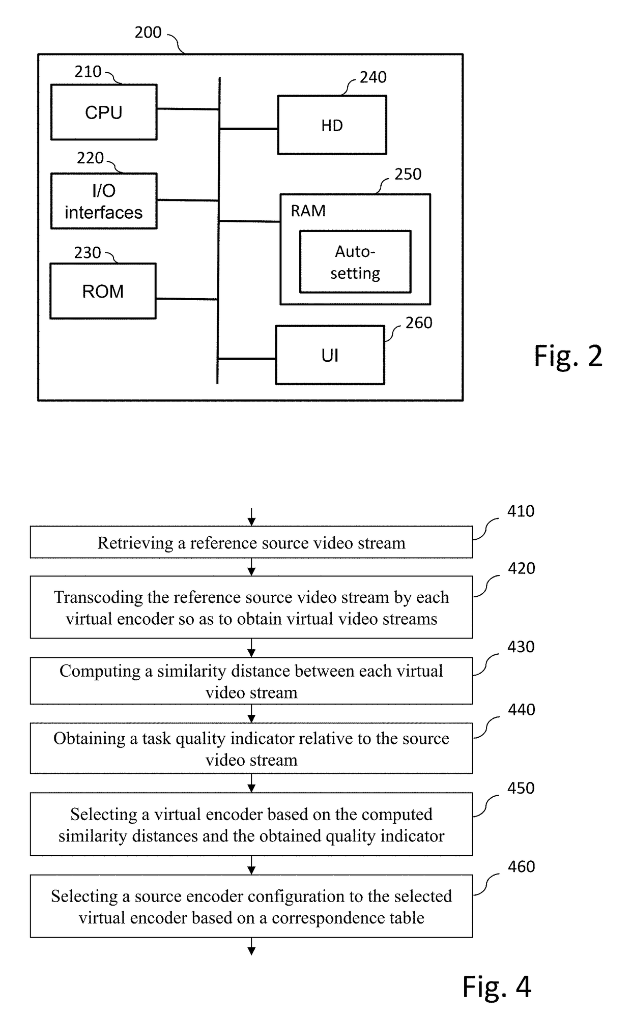
At least one embodiment of a method of configuring a video source comprising an embedded encoder for generating a stream, in a video-surveillance system comprising virtual encoders generating virtual streams, the method comprising:transcoding a reference stream generated by the video source to generate virtual streams according to distinct encoding configurations of the virtual encoders;for each of the generated virtual streams, computing a similarity distance between the corresponding virtual stream and a reference stream generated by the video source;obtaining a quality indicator relative to a task to be carried out on a stream generated by the video source;selecting an encoding configuration of a virtual encoder based on the computed similarity distances and the obtained quality indicator; anddetermining at least one configuration parameter value of the encoder of the video source as a function of the selected encoding configuration of the virtual encoder and of a look-up table.

Description

CROSS REFERENCE TO RELATED APPLICATION[0001]This application claims the benefit under 35 U.S.C. § 119(a)-(d) of United Kingdom Patent Application No. 1620011.5, filed on Nov. 25, 2016 and entitled “method and system for determining encoding parameters of video sources in large scale video surveillance systems”. The above cited patent application is incorporated herein by reference in its entirety.FIELD OF THE INVENTION[0002]The present invention relates to the technical field of video surveillance systems and more particularly to a method and a system for determining encoding parameters of video sources in large scale video surveillance systems.BACKGROUND OF THE INVENTION[0003]Video surveillance is currently a fast-growing market tending to become increasingly widespread for ubiquitous applications. It can be used today in numerous areas such as crime prevention, private and public areas for security purposes, abnormal events detection, traffic monitoring, customer behaviour, or gen...

Claims


Application Information

Patent Timeline
Patent Type & Authority Applications(United States)
IPC IPC(8): H04N19/40H04N7/18H04N7/01H04N19/154H04N19/136H04N19/85H04N19/103H04N19/124H04N19/184
CPCH04N19/40H04N7/181H04N7/0102H04N19/154H04N19/136H04N19/85H04N19/103H04N19/124H04N19/184H04N19/172H04N19/196H04N19/132H04N19/146H04N19/114H04N19/115H04N19/119H04N19/12H04N19/177H04N7/18
Inventor SEVIN, JULIENVISA, PIERRE
Owner CANON KK
Learn More