
Electrical Circuit and Display Apparatus

a technology of electric circuit and display apparatus, applied in the field of electric circuit, can solve the problems of insufficient reduction of emi noise by scramble processing, emi noise, and and achieve the effect of reducing the occurrence of emi noise more reliably

Active Publication Date: 2018-05-31
SAKAI DISPLAY PROD
View PDF21 Cites 6 Cited by
  • Summary
  • Abstract
  • Description
  • Claims
  • Application Information

AI Technical Summary

Benefits of technology

The invention is an electrical circuit that reduces EMI noise in data transmission through multiple buses. It uses a delay unit and a scrambler to perform processing on data frames during communication. This results in a more reliable display of images on a liquid crystal display panel. The circuit can also reduce EMI noise without adding extra parts, such as gaskets.

Problems solved by technology

Conventionally, in communication of data between a transmission device and a reception device using a plurality of buses, a problem of electro magnetic interference (EMI) noise has occurred.
However, in the present day when a communication speed of data is more increased, to reduce the EMI noise by the scramble processing is not sufficient.
Thereby, an interference between the buses has occurred to cause the EMI noise.
However, in Patent Document 1, for such a problem caused in the case of using the plurality of buses, any research has not been undertaken and therefore such a problem has yet to be solved.

Method used


Image

  • Electrical Circuit and Display Apparatus
  • Electrical Circuit and Display Apparatus
  • Electrical Circuit and Display Apparatus

Examples


embodiment 1

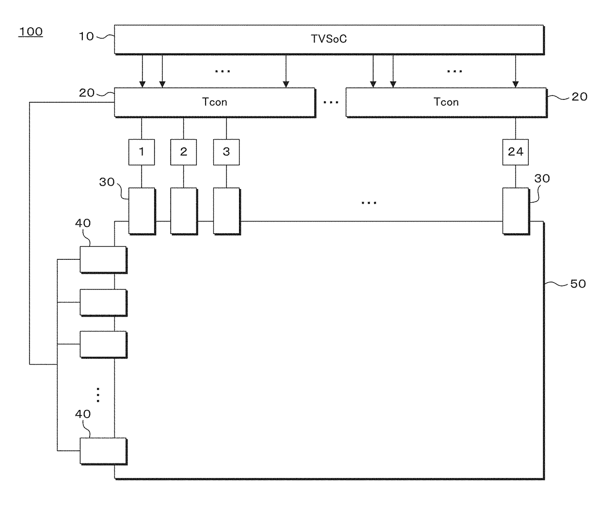
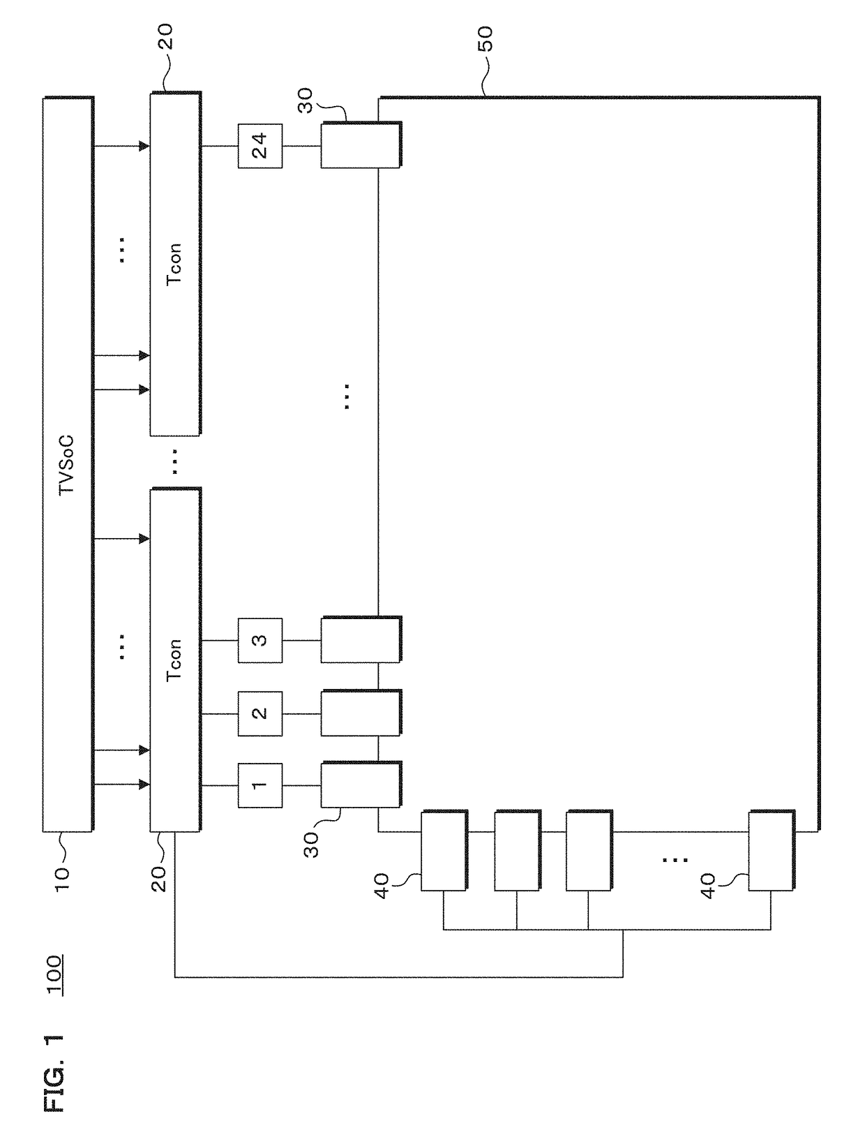
[0033]FIG. 1 is a functional block diagram illustrating a configuration of main components of a liquid crystal television 100 according to Embodiment 1.

[0034]The liquid crystal television 100 includes a TV system on a chip (TVSoC) 10 (a transmission unit), a plurality of timing controllers (Tcons) 20 configured to receive data from the TVSoC 10, a plurality of source drivers 30 (reception units) configured to receive the data from the Tcons 20 (the transmission units and reception units), and gate drivers 40. The source drivers 30 and the gate drivers 40 are connected to a liquid crystal display panel 50 on which an image is displayed based on such the data.

[0035]The electrical circuit described in the claims includes, for example, the TVSoC 10 and the Tcons 20, or the Tcons 20 and the source drivers 30.

[0036]The TVSoC 10, which is a so-called television reception circuit, receives a CVBS signal, an HDMI (registered trademark) signal, and the like to generate a television image, and...

embodiment 2

[0063]The present invention is not limited to the liquid crystal television 100 described in Embodiment 1.

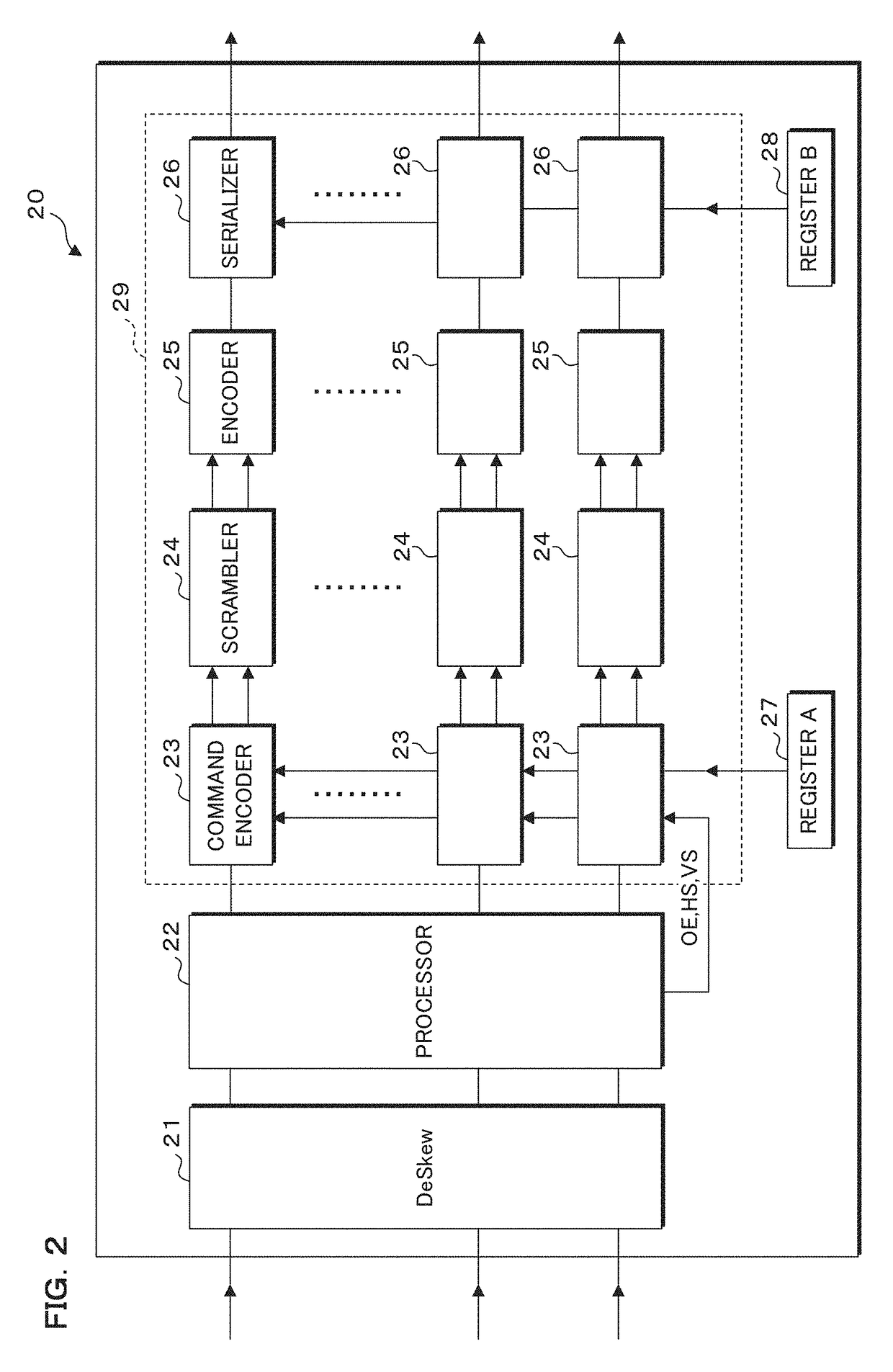
[0064]In a liquid crystal television 100 according to Embodiment 2, each of scramblers 24 is configured so as to perform scramble processing at a different timing for each bus. Thereby, during the communication of the data frames between the Tcon 20 and the source drivers 30, the scramble processings may be performed at a different timing in the communication times of the data frames for each bus, which will be described in detail below.

[0065]In the liquid crystal television 100 according to Embodiment 2, there is no delay in the output of data frame in each bus, but the scramble processings are performed on the data frames at a respectively different timing by each scrambler 24 corresponding to each bus.

[0066]FIG. 6 is a timing chart describing processing in which each scrambler 24 of the liquid crystal television 100 according to Embodiment 2 performs the scramble processing a...


PUM


Abstract

Provided are an electric circuit and a display device having the electric circuit. The electric circuit comprises a transmission unit and one or more reception units that perform data frame communications with the transmission unit via a plurality of buses. In the electric circuit, scramble processing is performed during the data frame communications, wherein the scramble processing is performed at different timings for the respective buses with respect to the data frame communication time, whereby the occurrence of EMI noise can be more reliably reduced without increasing the number of components (for example, gaskets).

Description

CROSS-REFERENCE TO RELATED APPLICATIONS[0001]This application is the national phase under 35 U.S.C. § 371 of PCT International Application No. PCT / JP2015 / 064485 which has an International filing date of May 20, 2015 and designated the United States of America.BACKGROUNDTechnical Field[0002]The present invention relates to an electrical circuit which includes a transmission unit and one or a plurality of reception units for performing communication of data frames with the transmission unit through a plurality of buses, and is configured to perform scramble processing during the communication of the data frames, and a display apparatus.Description of Related Art[0003]Conventionally, in communication of data between a transmission device and a reception device using a plurality of buses, a problem of electro magnetic interference (EMI) noise has occurred.[0004]For the EMI noise problem, scramble processing using a so-called random number is known in an existing electric equipment havin...

Claims


Application Information

Patent Timeline
Patent Type & Authority Applications(United States)
IPC IPC(8): G09G3/20G09G3/36H04N5/38H04N5/44
CPCG09G3/2096G09G3/36H04N5/38H04N5/44G09G2330/06G09G2310/08H04L25/03866
Inventor YABUKI, HARUHITO
Owner SAKAI DISPLAY PROD
Learn More