
Dome-type three-axis gimbal

a gimbal and three-axis technology, applied in the field of gimbal structure, can solve the problems of inability to control the rotation of the gimbal of fig. 1, cannot be used in a flight vehicle such as a rotor blade drone or a multi-copter capable of making a sharp turn, and is highly vulnerable to external disturbances, so as to achieve a small driving force and stable driving

Inactive Publication Date: 2018-05-31
HANWHA TECHWIN CO LTD
View PDF5 Cites 21 Cited by
  • Summary
  • Abstract
  • Description
  • Claims
  • Application Information

AI Technical Summary

Benefits of technology

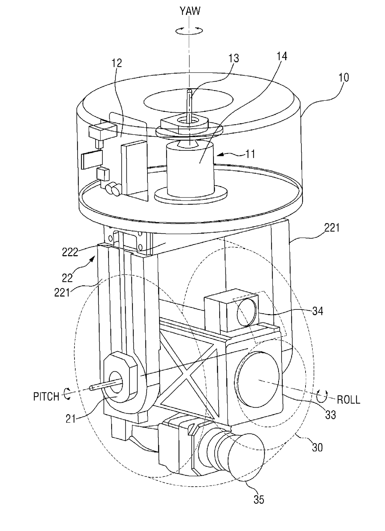
The present invention describes a three-axis rotatable gimbal that uses a dome-type housing. This design allows for stable driving even in the presence of disturbances, and enables the desired gimbal movement to be achieved with minimal driving force. The technical effect of this innovation is improved stability and efficiency in gimbal control.

Problems solved by technology

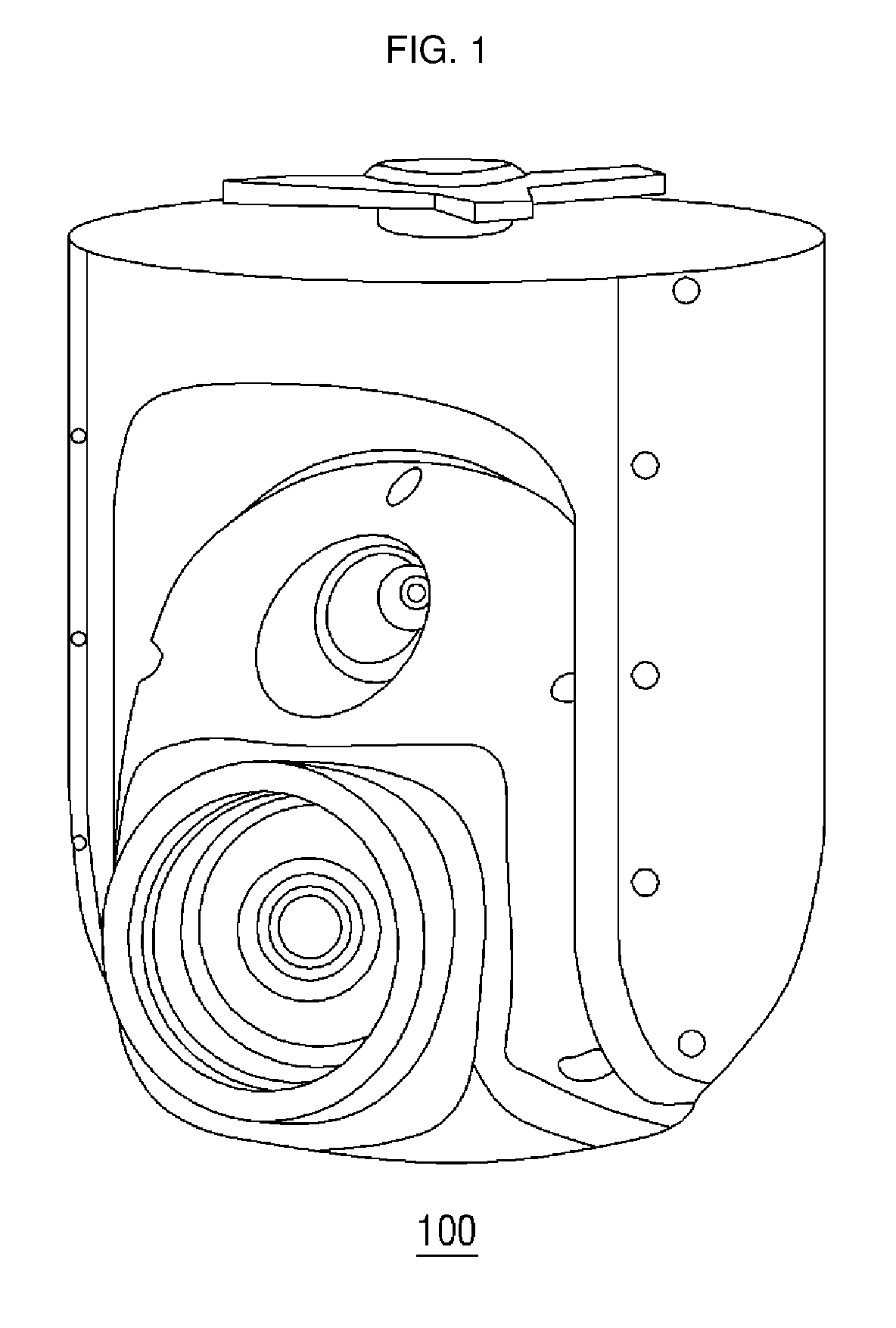
However, the gimbal of FIG. 1 is a two-axis gimbal capable of controlling yaw rotation and pitch rotation, and thus cannot control roll rotation.
Although the gimbal 100 of FIG. 1 has a dome-type housing and can thus be safeguarded from disturbance, the gimbal of FIG. 1 cannot be used in a flight vehicle such as a rotor blade drone or a multicopter capable of making a sharp turn.
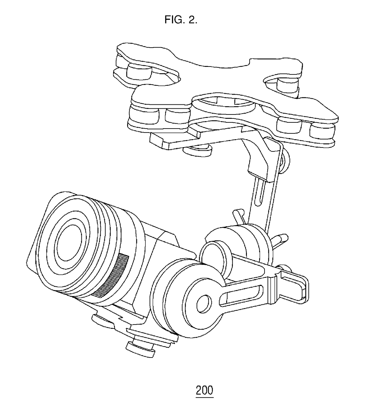
However, as is apparent from FIG. 2, the three-axis gimbal 200 has no designated housing for protecting an internal gimbal structure and a camera from an external environment and may thus be highly vulnerable to external disturbances.
However, because the servo motors need to be feedback-controlled using measurements provided by an encoder and are connected to gears to drive the rotary shafts, a backlash phenomenon may occur in connection with the gear heads, and this is not advantageous in reducing the weight and volume of the entire three-axis gimbal.

Method used


Image

  • Dome-type three-axis gimbal
  • Dome-type three-axis gimbal
  • Dome-type three-axis gimbal

Examples


Embodiment Construction

[0063]The present inventive concept will now be described more fully hereinafter with reference to the accompanying drawings, in which exemplary embodiments are shown. This inventive concept may, however, be embodied in different forms and should not be construed as limited to the exemplary embodiments set forth herein. Rather, these exemplary embodiments are provided so that this disclosure will be thorough and complete, and will filly convey the scope of the inventive concept to those skilled in the art. The same reference numbers indicate the same components throughout the specification. In the attached figures, the thickness of layers and regions is exaggerated for clarity.

[0064]Unless defined otherwise, all technical and scientific terms used herein have the same meaning as commonly understood by one of ordinary skill in the art to which this disclosure belongs. It is noted that the use of any and all examples, or exemplary terms provided herein is intended merely to better ill...


PUM


Abstract

A three-axis gimbal includes: a first housing including a first rotary shaft, the first rotary shaft configured to rotate the first housing in a first direction; a first bracket attached to, and extending from the first housing; a second bracket including second rotary shafts, the second rotary shafts rotatably supported by the first bracket, the second bracket configured to be rotatable in a second direction; a camera module including a third rotary shaft, the third rotary shaft rotatably supported on the second bracket, the camera module configured to be rotatable in a third direction; and a second housing accommodating the second rotary shafts and the third rotary shaft.

Description

CROSS-REFERENCE TO RELATED PATENT APPLICATION[0001]This application claims priority from Korean Patent Application No. 10-2016-0160354, filed on Nov. 29, 2016 the disclosure of which is incorporated herein by reference in its entirety.BACKGROUND1. Field[0002]Apparatuses consistent with exemplary embodiments relate to a gimbal structure of a camera for an unmanned aerial vehicle (UAV), and more particularly, to a dome-type three-axis rotatable gimbal.2. Description of the Related Art[0003]As unmanned aerial vehicles (UAVs) increasingly become popular, and the interest in cameras that are coupled to, and used along with, the UAVs has increased. Cameras used in the UAVs need to be light in weight and compact in size so that the UAVs can capture images while flying in an extended time in any given conditions, and so that unnecessary air resistance can be prevented.[0004]In the related art, a camera used in a UAV has a gimbal structure which maintains level so as to be able to stably cap...

Claims


Application Information

Patent Timeline
Patent Type & Authority Applications(United States)
IPC IPC(8): G03B17/56F16M13/02F16M11/06F16M11/18H04N5/232
CPCG03B17/561F16M13/022G03B15/006F16M11/18H04N5/2328F16M11/06F16M11/105F16M11/123F16M11/2064F16M13/02F16M2200/041F16M2200/044H04N23/685H04N23/20G03B11/00H04N23/57H04N5/33
Inventor KIM, SEUNG JINLEE, SANG RYEOL
Owner HANWHA TECHWIN CO LTD
Learn More