Vibration sound-producing apparatus

Active Publication Date: 2018-05-24
GOERTEK INC
View PDF0 Cites 7 Cited by
  • Summary
  • Abstract
  • Description
  • Claims
  • Application Information

AI Technical Summary

Benefits of technology

The present invention provides a vibration sound-producing apparatus with improved thin-type design and good performance. The apparatus has a sound hole in the lateral surface of the housing, which avoids the requirement on thickness of the external portable electronic terminal in the vertical direction due to a front sound hole, and avoids blocking of the sound hole due to insufficient thickness in the vertical direction of the electronic terminal. The vibrating diaphragm of the vibration system corresponds to the sound hole, and the voice coil vibrates in the horizontal direction and drives the vibrating diaphragm to vibrate and generate sound through the transmission structure. The flat structure of the voice coil allows for a larger space for vibration and increases the amplitude, improving the performance of the vibration sound-producing apparatus. The magnet comprises a first magnet portion and a second magnet portion, which are provided at two sides of the voice coil respectively and in parallel with the voice coil, effectively improving the magnetic field strength inside the vibration sound-producing apparatus, improving the acting force applied to the conductive voice coil, and improving the product performance.

Problems solved by technology

The vibration speaker with such a structure is limited in the volume of the cylindrical voice coil and the space for vibration of the cylindrical voice coil, and a mass block combined with the magnetic circuit system is further required to be provided in the vertical direction, which thickens the thickness in the vertical direction and cannot meet the requirement on thin-type of the product.
With the improvements on thin-type and miniaturization design of the portable electronic terminal, the existing vibration sound-producing apparatus cannot meet the development trend of thin-type and miniaturization.

Method used


Image

  • Vibration sound-producing apparatus
  • Vibration sound-producing apparatus
  • Vibration sound-producing apparatus

Examples


Embodiment Construction

[0025]Hereinafter, the contents of the present invention will be described in detail with reference to the accompanying drawings.

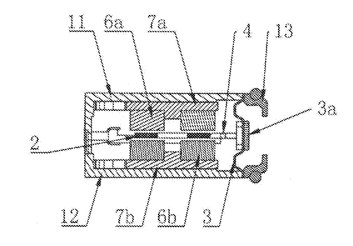
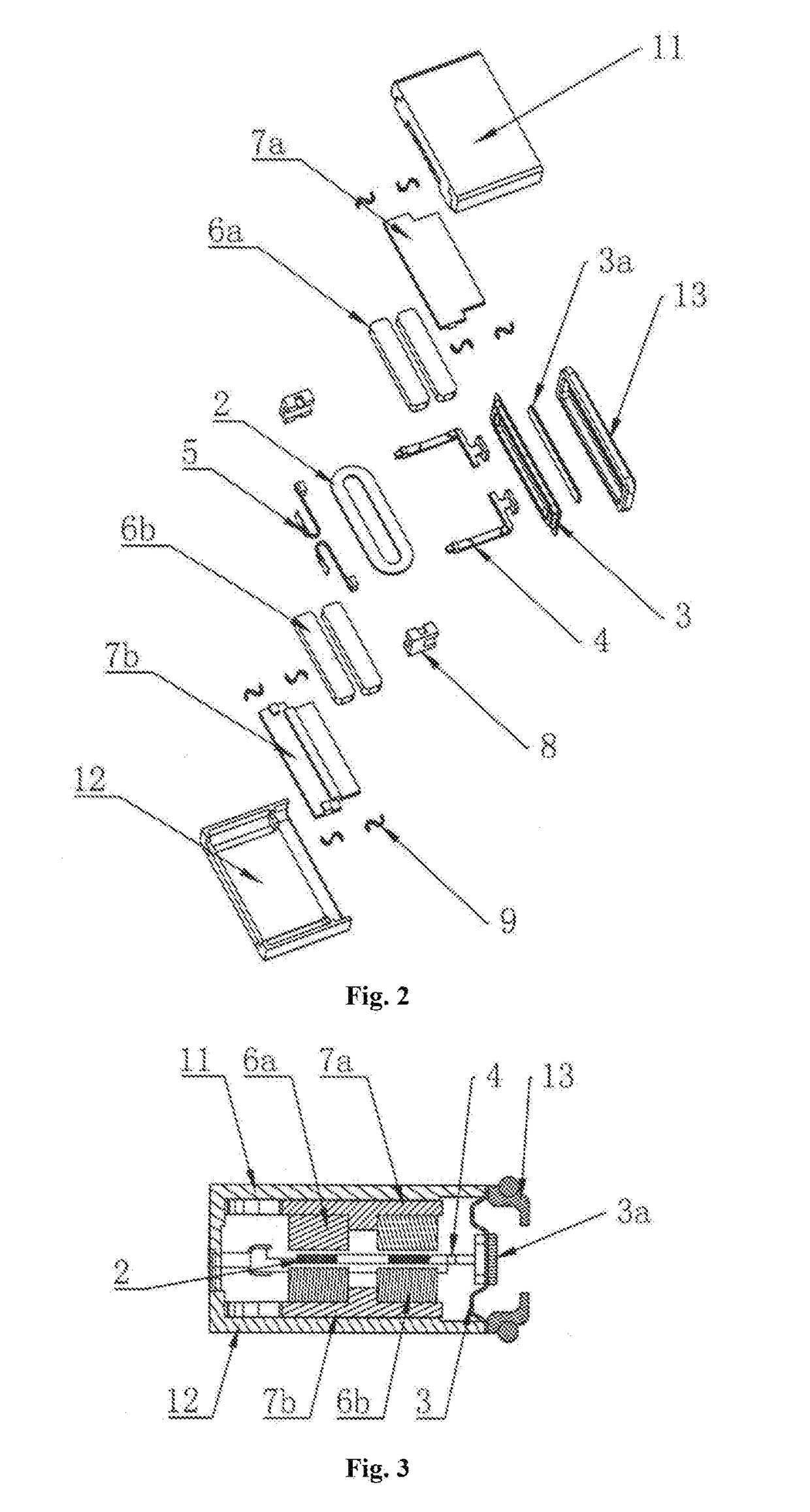
[0026]As shown in FIG. 2, the vibration sound-producing apparatus of the present invention comprises a housing, a vibration system and a magnetic circuit system. The housing comprises a first housing 11, a second housing 12, and a side cover 13 fixed to the side walls of the first housing 11 and the second housing 12. The vibration system and the magnetic circuit system are provided in the cavity defined by the first housing 11, the second housing 12, and the side cover 13. The side cover 13 is provided with a sound hole for emitting sound. As shown in FIGS. 2 and 3, the vibration system comprises a vibrating diaphragm 3, a voice coil 2, and a transmission structure 4. The vibrating diaphragm 3 is provided at a position facing the side cover 13 in which the sound hole is provided, that is, the vibrating diaphragm 3 is provided at a position adjacent to the...


PUM


Abstract

Disclosed is a vibration sound-producing apparatus. A sound output aperture is provided on a sidewall perpendicular to a thickness direction. A diaphragm is parallel to the plane on which the sound output aperture is located. A flat sound coil is perpendicular to the diaphragm. Two magnets parallel to the sound coil are arranged at either side of the sound coil. The vibrating direction of the sound coil avoids the thickness direction. The vibrating direction of an integral structure of the magnets and a magnetic conductor part also avoids the thickness direction. This facilitates a thickness-reduced design for a product, increases the space for vibration, and enhances product performance, meanwhile, the design of the two magnets effectively increases the strength of the magnetic field within the product, this further improving product performance. The vibration sound-producing apparatus of the present invention has the advantages of a great thickness-reduced design and great performance.

Description

TECHNICAL FIELD[0001]The present invention relates to the technical field of electroacoustics, and more particularly, to a vibration sound-producing apparatus.BACKGROUND ART[0002]A vibration speaker is a multi-functional acoustic device, which may not only achieve the vibration sound-producing functionality as an ordinary speaker, but also achieve the functionality of a vibrating motor. The vibration speaker may save the internal space of a portable electronic terminal, simplify the assembly process of the portable electronic terminal, and reduce the cost of the portable electronic terminal. Therefore, the vibration speaker has been increasingly and widely used in the field of portable electronic terminal.[0003]The existing vibration sound-producing apparatus with a conventional structure comprises a vibration system and magnetic circuit system. The vibration system comprises a vibrating diaphragm, and a cylindrical voice coil which is integrated with the vibrating diaphragm. The ma...

Claims


Application Information

Patent Timeline
IPC IPC(8): H04R9/02H04R9/06H04R1/38
CPCH04R9/025H04R9/06H04R1/38H04R3/002H04R7/16H04R9/047H04R3/00
Inventor ZHU, YUEGUANGSUN, HONGCHAOXU, CHAO
Owner GOERTEK INC
Why Eureka
Try Eureka