Connector structure and electric vehicle

a technology of connecting structure and connector, applied in the direction of charging station, transportation and packaging, coupling device connection, etc., can solve the problems of increasing manufacturing man-hours, increasing design man-hours, and large size of the entire connector fitting structure, so as to reduce the number of parts, reduce the cost, and increase or decrease the effect of connectors

Active Publication Date: 2018-05-24
HONDA MOTOR CO LTD
View PDF13 Cites 7 Cited by
  • Summary
  • Abstract
  • Description
  • Claims
  • Application Information

AI Technical Summary

Benefits of technology

[0032][9] According to the first aspect of the present invention, the first inclined portion and the second inclined portion may be formed integrally with the second busbar. By punching the second busbar, it is possible to easily form the first inclined portion and the second inclined portion in the second busbar, and contribute to cost reduction.
[0033][10] According to the first aspect of the present invention, a housing configured to protect an outer periphery may be attached to one or more connectors of the plurality of connectors except the unused connector, and, instead of the housing, the cover may be attached in advance to the unused connector of the plurality of connectors. Consequently, the unused connector does not need the housing, so that it is possible to reduce the number of parts.
[0034][11] An electric vehicle according to a second aspect of the present invention includes the connector structure according to the first aspect of the present invention. Consequently, it is possible to easily increase or decrease the number of connectors installed in the connector structure according to the number of accessories mounted on the electric vehicle, and easily cope with car models having a large number of accessories.
[0035][12] According to the second aspect of the present invention, the connector structure may be mounted on a casing of a power converting device or a battery. By directly mounting the connector structure on the power converting device or the battery, it is possible to reduce the number of parts. It is possible to use a common connector shape between different car models, and use a common mounting point for a high voltage casing, too. As a result, it is possible to reduce man-hours of a high voltage casing design.
[0036][13] According to the second aspect of the present invention, the connector structure may be arranged on a rear surface of the power converting device in a vehicle longitudinal direction. The connector structure is connected with a plurality of high voltage connectors. Even when frontal collision occurs, by arranging the connector structure on the rear surface of the power converting device, it is possible to effectively prevent fracture of the connector structure and exposure of a high voltage portion due to detachment of the fitted connector, while reducing reinforcing members or the like.
[0037]According to the connector structure and the electric vehicle according to the present invention, even when various car models and specifications increase the number of components, it is not necessary to newly change a connector shape (the entire structure, the busbars, the fuses, etc.), and it is possible to reduce the design man-hours, and reduce manufacturing cost.

Problems solved by technology

According to Japanese Patent No. 3843074 and Japanese Laid-Open Patent Publication No. 2012-155943, there is a concern that when the number of components of a vehicle increases, it is necessary to newly redesign a connector group (a cover, a shield shell, busbars and mounting points), which leads to an increase in design man-hours, an increase in inventory control man-hours and an increase in manufacturing man-hours.
There is also a problem that a size of the entire connector fitting structure is large.

Method used


Image

  • Connector structure and electric vehicle
  • Connector structure and electric vehicle
  • Connector structure and electric vehicle

Examples


first embodiment

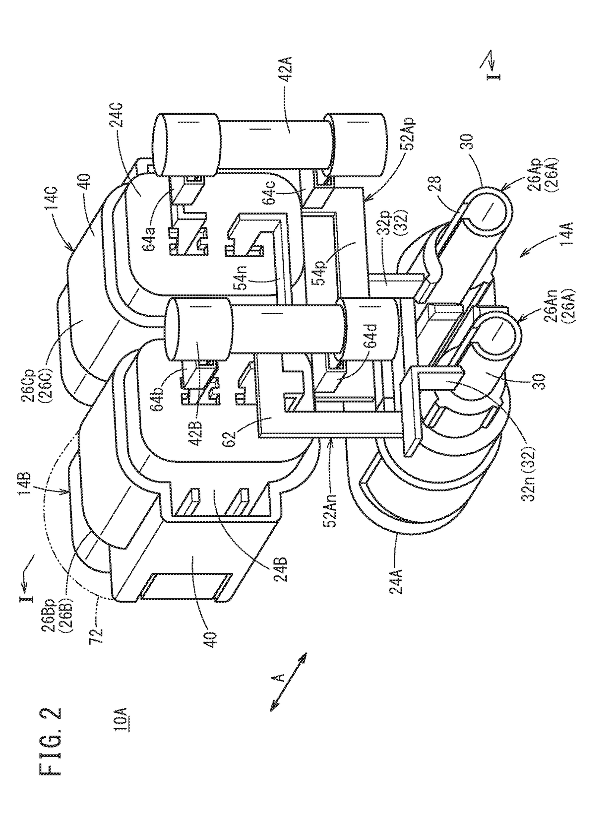
[0051]FIG. 1 is a cross-sectional view (a cross-sectional view on a I-I line in FIG. 2) showing a connector structure (referred to as a first connector structure 10A below) according to a FIG. 2 is a view showing a rear side of the first connector structure 10A from which a connector casing 12 described below is detached in particular. FIG. 3 is an exploded perspective view of the first connector structure 10A.

[0052]This first connector structure 10A is a connector structure that is installed in an electric vehicle 100 such as a hybrid vehicle, a plug-in hybrid vehicle, an electric automobile, or a fuel-cell vehicle, and supplies power to high voltage accessories (components). The accessories include, for example, a water heater, an A / C electric compressor, a charger provided to a PHEV, a quick charger, and a non-contact charging rectifier.

[0053]More specifically, the first connector structure 10A includes the connector casing 12 whose outer shape is made of, for example, a resin, ...

second embodiment

[0079]Next, a connector structure (referred to as a second connector structure 10B below) will be described with reference to FIG. 6.

[0080]As shown in FIG. 6, the second connector structure 10B includes the two first connector structures (sub-connector structures) 10A. More specifically, in the expanded portion 38 of the cylindrical portion 30 of the first connector structure 10A, an end portion opposite to the expanded portion 38 of the cylindrical portion 30 of another first connector structure 10A is inserted for electrical connection.

[0081]In this case, one first connector structure 10A can include three mounted side connectors. However, this second connector structure 10B can include two more mounted side connectors. That is, the second connector structure 10B can include the five mounted side connectors.

[0082]Consequently, by sequentially connecting the end portion opposite to the expanded portion 38 of the cylindrical portion 30 of another first connector structure 10A to th...

third embodiment

[0102]As schematically shown in FIGS. 10A to 10C, a connector structure 10C (referred to as a third connector structure 10C) employs different configurations of electrode conductive portions of the mounting side connector 110 and the mounted side connector 112 from the example in FIGS. 9A and 9B. The mounting side connector 110 corresponds to the above mounting side connector 34, and the mounted side connector 112 corresponds to the above first mounted side connector 14A or the like.

[0103]That is, the mounting side connector 110 includes the first busbar 116A that constitutes the first electrode conductive portion 114A and extends in the mounting direction, and a hole 120 that is formed in the first busbar 116A.

[0104]The mounted side connector 112 includes the second busbar 116B that constitutes the second electrode conductive portion 114B and extends in the mounting direction, a first inclined portion 124A that is raised in one direction from a plate surface 122 of the second busb...


PUM


Abstract

A connector structure installed in the electric vehicle includes a plurality of connectors, an inter-connector conductive member configured to electrically connect the plurality of connectors, and a connector casing configured to house the inter-connector conductive member. A cover is attached to the unused connector of the plurality of connectors.

Description

CROSS-REFERENCE TO RELATED APPLICATION[0001]This application is based upon and claims the benefit of priority from Japanese Patent Application No. 2016-228051 filed on Nov. 24, 2016, the contents of which are incorporated herein by reference.BACKGROUND OF THE INVENTIONField of the Invention[0002]The present invention relates to a connector structure that is installed in a vehicle, for example, and supplies power to accessories, and an electric vehicle in which the connector structure is installed.Description of the Related Art[0003]A task of a connector fitting structure disclosed in Japanese Patent No. 3843074 is to easily fit and detach a plurality of connectors and easily replace fuses in the connectors.[0004]To achieve the above task, the connector fitting structure adopts a structure including a slide structure that is movably arranged in a connector fitting direction in one connector group and includes a temporary locking unit for the other connector group, and a bolt that is ...

Claims


Application Information

Patent Timeline
Patent Type & Authority Applications(United States)
IPC IPC(8): H01R13/68B60L11/18H01R13/64H01R13/703H01R13/405B60K6/22
CPCH01R13/68B60L11/1818H01R13/64H01R13/703H01R13/405B60K6/22H01R2201/26H01R13/02H01R13/502H01R13/5213H01R13/688H01R24/00H01R27/00B60L53/16Y02T10/70Y02T10/7072Y02T90/14Y02T90/12
Inventor KIYUNA, MIHARUOZAKI, YUSUKESUZUKI, TOMOYUKIUNO, AYUMUKUME, YASUHISAKAWAHARA, MAKOTO
Owner HONDA MOTOR CO LTD
Why Eureka
Try Eureka