Braking control apparatus for vehicle

a technology for controlling apparatus and vehicle, which is applied in the direction of brake systems, etc., can solve the problems of difficult to apply an effective anti-spin moment to the vehicle, and achieve the effects of ensuring the stability of the braking device, enhancing the acceleration performance, and increasing the braking for

Active Publication Date: 2018-05-24
TOYOTA JIDOSHA KK +1
View PDF4 Cites 8 Cited by
  • Summary
  • Abstract
  • Description
  • Claims
  • Application Information

AI Technical Summary

Benefits of technology

[0018]In the second aspect, the electronic control unit may be configured to, when the deflection direction of the vehicle is reversed during performance of the right and left wheel independent control in the high-speed range, increase a braking force of the rear wheel located on the outside during occurrence of deflection of the vehicle after reversal of the deflection direction of the vehicle, and prohibit the braking pressure of the rear wheel located on the inside during occurrence of deflection after reversal of the deflection direction from being increased, after the predetermined time passes from the time point of reversal of the deflection direction.
[0019]According to the disclosure, right and left wheel independent control is performed to control the braking pressures of the rear-right wheel and the rear-left wheel independently of each other such that the slip degree of each of the rear-right wheel and the rear-left wheel approaches the target slip degree as the average of the slip degrees of the front-right wheel and the front-left wheel. In the high-speed range of the vehicle, this right and left wheel independent control is started as soon as the deceleration (the second predetermined value) that is smaller than the deceleration (the first predetermined value) of the vehicle at the time when right and left wheel independent control is started in the low-speed range is reached. Thus, an environment in which the rear-wheel small braking force characteristics (the chara

Problems solved by technology

When the braking forces of both the rear-right wheel and the rear-left wheel are increased in this manner through the adjustment of the braking pressures thereof, the enhancemen

Method used


Image

  • Braking control apparatus for vehicle
  • Braking control apparatus for vehicle
  • Braking control apparatus for vehicle

Examples


first embodiment

[0028][Configuration of First Embodiment]

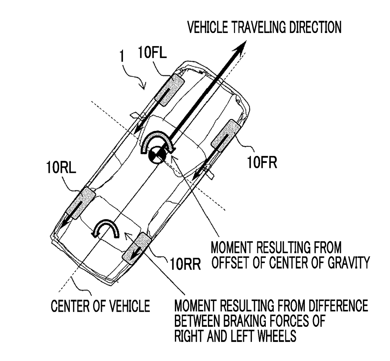
[0029]FIG. 1 is a conceptual view representing an exemplary configuration of a vehicle 1 to which a braking control apparatus according to the first embodiment of the disclosure is applied. As shown in FIG. 1, the vehicle 1 according to the present embodiment of the disclosure is equipped with four wheels 10. In the following description, the front-right wheel, the front-left wheel, the rear-right wheel, and the rear-left wheel will be denoted by 10FR, 10FL, 10RR, and 10RL respectively. Besides, the front wheels may be comprehensively denoted by 10F, and the rear wheels may be comprehensively denoted by 10R.

[0030]The vehicle 1 is equipped with a steering device 12 having a steering wheel 12a. The steering device 12 is configured to change the direction of the front wheels 10F as steered wheels of the vehicle 1, in accordance with the operation of the steering wheel 12a by a driver.

[0031]The vehicle 1 is equipped with a brake device 20. The br...


PUM


Abstract

A braking control apparatus performs right and left wheel independent control to approach a slip rate of a rear-right wheel and a rear-left wheel to a target slip rate as an average of slip rates of a front-right wheel and a front-left wheel. In a high-speed range, right and left wheel independent control is started when a deceleration is equal to or larger than a start value that is smaller than a start value used in a low-speed range. In right and left wheel independent control started in the high-speed range, when there is a demand to increase braking pressures of both the rear-right wheel and the rear-left wheel, the braking pressure of the rear wheel located on the outside during the occurrence of deflection of the vehicle resulting from braking is increased, and the braking pressure of the rear wheel located on the inside is prohibited from increasing.

Description

INCORPORATION BY REFERENCE[0001]The disclosure of Japanese Patent Application No. 2016-228191 filed on Nov. 24, 2016 including the specification, drawings and abstract is incorporated herein by reference in its entirety.BACKGROUND1. Technical Field[0002]This disclosure relates to a braking control apparatus for a vehicle, and more particularly, to a braking control apparatus that is suited to control a vehicle in which right and left-wheel independent control for controlling braking pressures of a rear-right wheel and a rear-left wheel independently of each other is performed.2. Description of Related Art[0003]In Japanese Patent Application Publication No. 2012-096610 (JP 2012-096610 A), there is disclosed a vehicular braking force control apparatus capable of controlling braking pressures of a rear-right wheel and a rear-left wheel independently of each other. According to this control apparatus, a braking pressure of each of a rear-right wheel and a rear-left wheel is individually...

Claims


Application Information

Patent Timeline
IPC IPC(8): B60T8/1766B60T8/18B60T8/58B60T8/1755
CPCB60T8/1766B60T8/18B60T8/58B60T8/17551B60T8/17552B60T8/1755B60T8/1761B60T8/32
Inventor HARA, MASAHIROYOSHII, YUJIYAMAMOTO, YUSAKUTERADA, HITOSHINAKANO, TAKUYAAKIBA, SHINYA
Owner TOYOTA JIDOSHA KK
Why Eureka
Try Eureka