
Gear cutting machine and method

a cutting machine and gear technology, applied in the direction of gear teeth, gear tooth manufacturing apparatus, manufacturing tools, etc., can solve the problems of high equipment cost, poor productivity of gear shaper machining, broach machining, etc., and achieve high efficiency gear machining and high precision. , the effect of prolonging the service life of the tool

Active Publication Date: 2018-05-24
MITSUBISHI HEAVY IND MACHINE TOOL CO LTD
View PDF0 Cites 0 Cited by
  • Summary
  • Abstract
  • Description
  • Claims
  • Application Information

AI Technical Summary

Benefits of technology

The gear cutting machine and method described in this patent can do high precision and high efficiency gear machining while extending the life of the tool.

Problems solved by technology

However, gear shaper machining has a problem with poor productivity because the machining time is long, and broach machining has problems with high equipment costs, difficulty in adjusting the machining precision, and limits on the shape of gears that can be machined.

Method used


Image

  • Gear cutting machine and method
  • Gear cutting machine and method
  • Gear cutting machine and method

Examples


embodiment

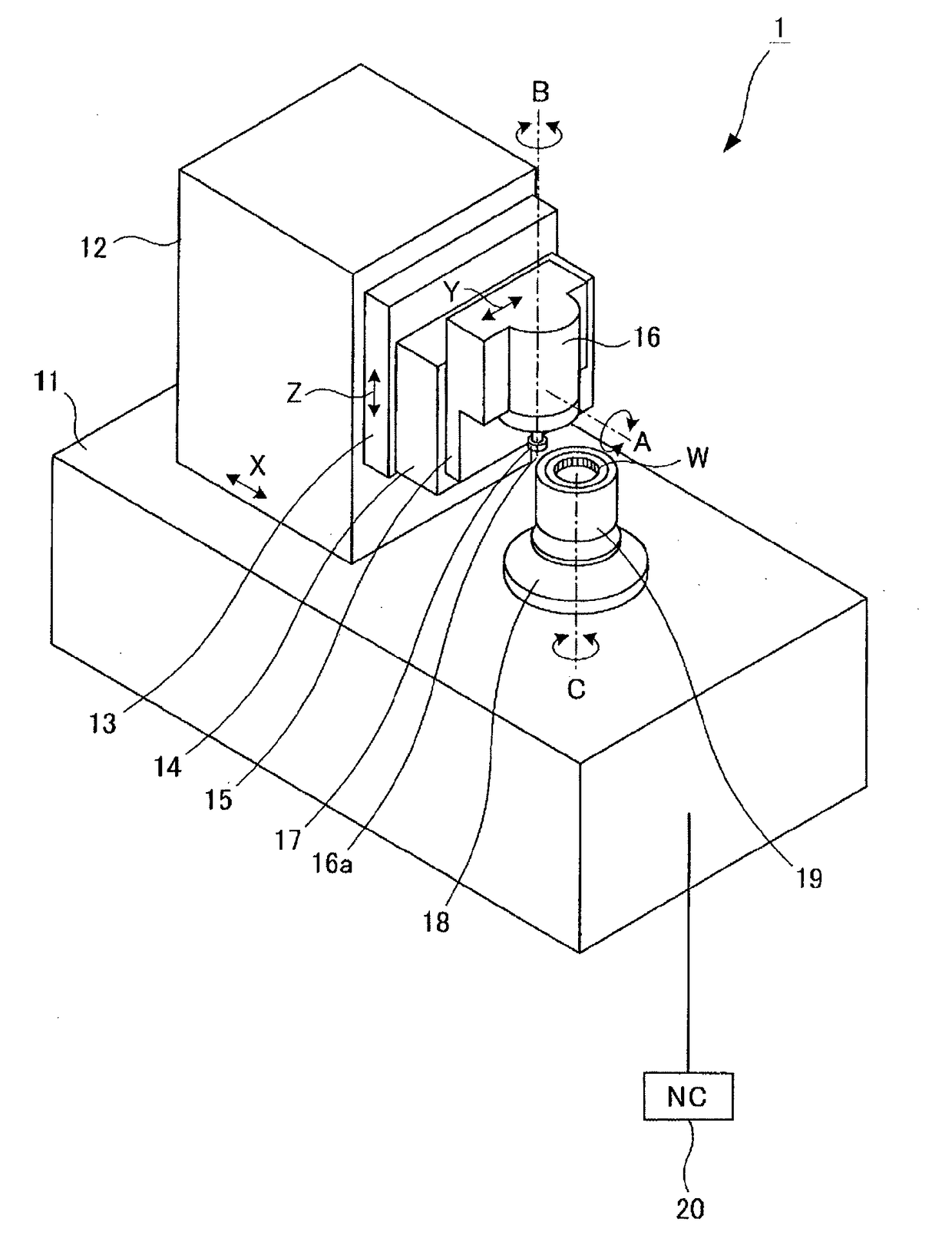
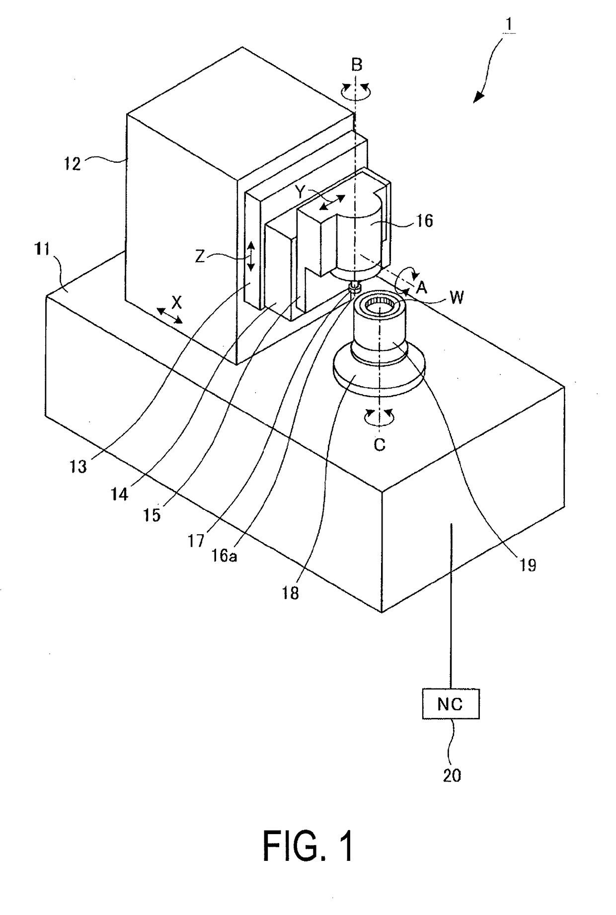
[0036]As illustrated in FIG. 1, a column (cutter cutting means) 12 is movably supported in a horizontal x-axis direction (cutting depth direction (however, herein the cutting depth direction refers to the cutting depth direction of rough cutting. In the present invention, the cutting depth direction changes during finish cutting, as described below)), on the bed 11 of the gear cutting machine (gear cutting machine 1) according to the present embodiment. In addition, a saddle (cutter feeding unit) 13 is supported on the front face of the column 12 in such a manner so as to be vertically moveable in the z-axis direction (feeding direction) orthogonal to the x-axis direction. Furthermore, a swivel head (swivel unit, crossed axis angle setting unit) 14 is supported on the front face of the saddle 13 in such a manner so as to be able to swivel about the cutter swivel axis A that extends in the x-axis direction.

[0037]In addition, a slide head (cutter moving means) 15 is movably supported ...


PUM


Abstract

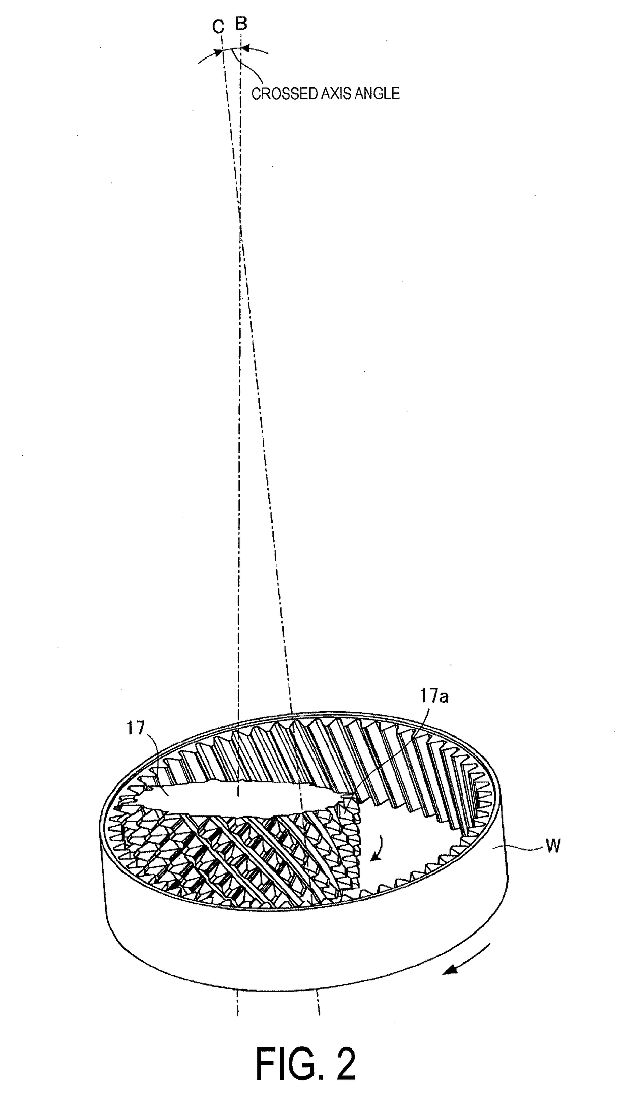
A gear cutting machine for gear cutting a workpiece (W) using a gear shaped cutter (17), by engaging and rotating the workpiece (W) that can rotate around a workpiece axis and a gear shaped cutter (17) that can rotate around a cutter axis, while cutting and feeding the gear shaped cutter (17), including:rough cutting at a cross axis angle to the cutter axis, then moving the cutter axis by moving a predetermined angle around the workpiece axis, and performing finish cutting such that the cutter axis has an angle with regard to the workpiece axis in a plane that includes the feeding axis direction and the cutting direction after moving.

Description

TECHNICAL FIELD[0001]The present invention relates to a gear cutting machine and method.BACKGROUND ART[0002]Currently, when performing gear cutting of stepped gears or internal gears that cannot be hob machined, gear shaper machining using a pinion cutter and broach machining using a helical broach are mainstream.[0003]However, gear shaper machining has a problem with poor productivity because the machining time is long, and broach machining has problems with high equipment costs, difficulty in adjusting the machining precision, and limits on the shape of gears that can be machined.[0004]Therefore, Patent Literature 1 discloses a method of cutting while rotating a pinion cutter rather than a reciprocal movement, thus achieving high precision and high efficiency gear cutting.CITATION LISTPatent Literature[0005]Patent Literature 1: JP-A-2015-58505SUMMARY OF INVENTIONTechnical Problems[0006]However, the gear cutting process disclosed in Patent Literature 1 has a problem in that the sam...

Claims


Application Information

Patent Timeline
IPC IPC(8): B23F5/16B23F21/10B23F23/12
CPCB23F5/163B23F21/10B23F23/1206B23F23/1231B23F5/16
Inventor USUDE, JUNJI
Owner MITSUBISHI HEAVY IND MACHINE TOOL CO LTD
Learn More