
Multi-channel fluorescence detection device

a fluorescence detection and multi-channel technology, applied in the field can solve the problems of difficult to meet requirements, bulky and heavy kind of fluorescence detection devices in the market, and increase the complexity of the fluorescence detection device, so as to achieve superior performance for multi-color qpcr applications and minimize the size and weight of the device.

Active Publication Date: 2018-05-10
DELTA ELECTRONICS INTL SINGAPORE
View PDF0 Cites 5 Cited by
  • Summary
  • Abstract
  • Description
  • Claims
  • Application Information

AI Technical Summary

Benefits of technology

The present invention aims to provide a multi-channel fluorescence detection device that is small and lightweight, but still capable of delivering superior performance for multi-color qPCR applications.

Problems solved by technology

However, when the fluorescent probes with different colors are required in an assay or multiple fluorescent probes are distributed laterally for detection, it drastically increased the complexity of the fluorescence detection device, and the requirements are difficult to suffice.
Moreover, even if the requirements are met, this kind of fluorescence detection device in the market is bulky and heavy, and misalignment between light sources, moveable PCR samples and detectors are also an issue.

Method used


Image

  • Multi-channel fluorescence detection device
  • Multi-channel fluorescence detection device
  • Multi-channel fluorescence detection device

Examples


Embodiment Construction

[0035]The present invention will now be described more specifically with reference to the following embodiments. It is to be noted that the following descriptions of preferred embodiments of this invention are presented herein for purpose of illustration and description only; it is not intended to be exhaustive or to be limited to the precise form disclosed.

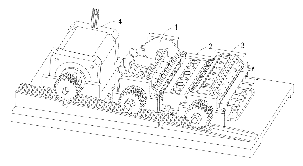
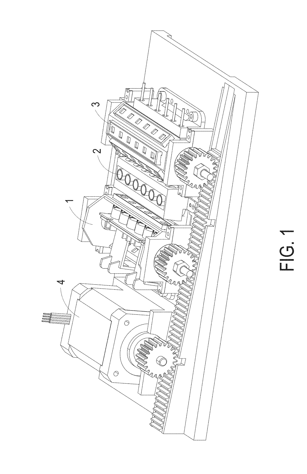
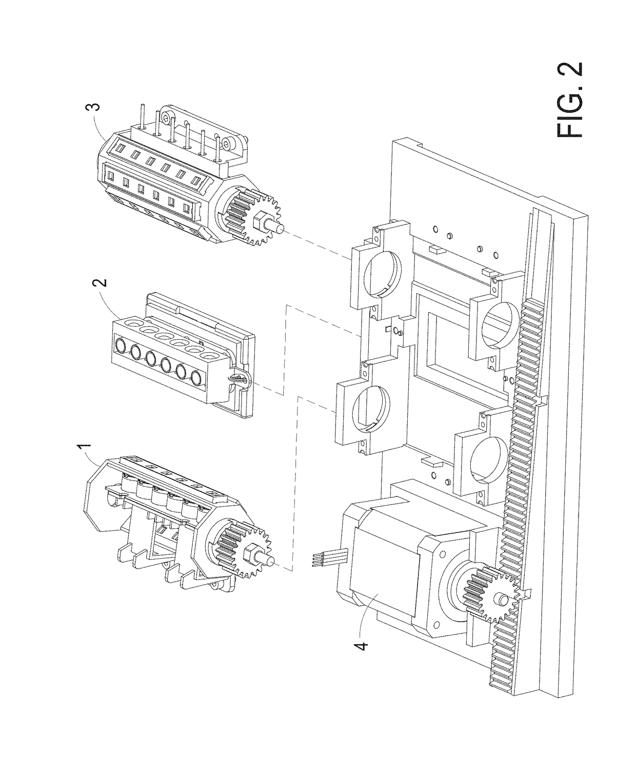
[0036]The present invention provides a multi-channel fluorescence detection device which is an optical module sequentially illuminating lights with four different colors on multiple fluorescent samples arranged in linear position. During the qPCR amplification process, this device provides light source with different colors to excite different fluorescent probes, and detect specific fluorescent signal emitted from the probes by rotating excitation and emission filters which are driven by two rotational drums simultaneously.

[0037]Please refer to FIGS. 1-3, wherein FIG. 1 shows a schematic view of the multi-channel fluorescence det...


PUM

PropertyMeasurementUnit
visible wavelengthsaaaaaaaaaa
deviation angleaaaaaaaaaa
back working distanceaaaaaaaaaa

Abstract

The multi-channel fluorescence detection device includes an illumination module, plural heating chambers, a detection module and a transmission module. The illumination module includes at least one light source, plural different types of excitation filters, and a first rotational drum, wherein the light source provides a broad band illumination, each of the excitation filters passes light at a particular band width for exciting a targeted fluorescent probe, and the first rotational drum drives the excitation filters. The plural heating chambers are adapted for accommodating PCR tubes having samples and the targeted fluorescent probes. The detection module includes plural different types of emission filters, a second rotational drum and at least one photo-detector, wherein each of the emission filters passes light at a particular band width, the second rotational drum drives the emission filters, and the photo-detector receives fluorescent signals and converts the fluorescent signals to electrical signals. The transmission module includes an actuator connecting with the first and the second rotational drums to drive rotations of the first and the second rotational drum simultaneously for switching and synchronizing the excitation filters and the emission filters to match specific wavelengths of the targeted fluorescent probes.

Description

FIELD OF THE INVENTION[0001]The present invention relates to a fluorescence detection device, and more particularly to a multi-channel fluorescence detection device.BACKGROUND OF THE INVENTION[0002]Due to the requirement of retrieving a particular segment of DNA in large quantities for different purposes, scientists need an efficient way to meet their goals. Polymerase chain reactions (PCR) is one of the cost-effective and time-saving techniques which could provide billion copies of specific DNA segments in short period of time. PCR technique could be applied in many fields, such as diagnosis of diseases in hospitals and biological research institutes, identification of bacteria and viruses, detection and monitoring of diseases, genomic mutation and cancer biomarkers, inspection of environmental hazards, investigation of criminals, and so on. PCR technique only requires small amount of DNA samples extracted from blood or tissues. By utilizing fluorescent dye into the nucleic acids s...

Claims


Application Information

Patent Timeline
Patent Type & Authority Applications(United States)
IPC IPC(8): C12Q1/68G01N21/64B01L7/00
CPCC12Q1/686G01N21/6428B01L7/52G01N2201/0633G01N2201/0638G01N2021/6419B01L2300/1822G01N2201/068G01N2201/062G01N2021/6439B01L2200/028B01L2200/025B01L2300/0654G01N2021/6421G01N21/0332G01N21/645G01N2021/6471
Inventor MA, BOHUANG, SONG-BINYIU, JEI-YINWANG, HUI
Owner DELTA ELECTRONICS INTL SINGAPORE
Learn More